| Author | Message | ||
Aphototaker Tinkerer Username: Aphototaker Post Number: 238 Registered: 12-2009 Rating: N/A |
CORRECTION in my last post, step 4-a: to install the wire, the functional resistor dial would need to be wound by turning it in counter-clockwise direction for a turn and a quarter. Here is a photo of the functional resistor (it is in the position where the shutter speed dial is removed). 1 (Magenta): The wire goes around the outer edge of the dial and goes in through the slot in the edge of the dial. 2 (Blue): Coming through the slot of the dial edge, it goes around the eccentric post and continues on ... 3 (Green) .. toward the tab with a slot. It goes through the slot and is wound (as far as I can see) around the tab. The black stuff is probably glue to hold the wire there. NB: The position shows (photo taken from front of the camera) the dial when the shutter speed dial is removed. The eccentric post is pointing toward the back of the camera, or at 6'o clock position if seen from behind the camera. With wire broken or uninstalled, it would be unwound and there will be no spring tension, the dial would have turned clockwise for around 1 and a quarter turn, i.e. the post would be then at around 9'o clock position and without any spring tension. 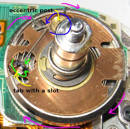 |