| Author |
Message |
    
Charlie
Tinkerer
Username: Charlie
Post Number: 173
Registered: 07-2006
Rating: N/A
Votes: 0 (Vote!) | | Posted on Friday, September 12, 2008 - 05:46 am: | 


|
Does anyone know where I can find a wiring diagram for a Konica Auto S2 or similar shutter priority/manual camera? Thanks for any search efforts, successful or not. |
    
Nickon51
Tinkerer
Username: Nickon51
Post Number: 19
Registered: 05-2008
Rating: N/A
Votes: 0 (Vote!) | | Posted on Monday, September 15, 2008 - 06:44 am: | 


|
Hi Charlie,
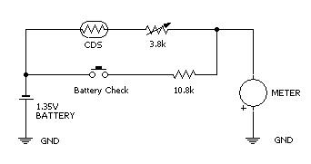
They are not terribly complex, just a battery, Cds cell, and meter in series. Some have a shunt resistor across the meter as well.
I'll try to upload a cct for the Konica Auto S2. The resistances are as measured in cct.
Cheers
Greg
 |
    
Charlie
Tinkerer
Username: Charlie
Post Number: 175
Registered: 07-2006
Rating: N/A
Votes: 0 (Vote!) | | Posted on Monday, September 15, 2008 - 02:19 pm: | 


|
Thanks Nickon, but I was more interested in a point to point wiring diagram for a shutter priority camera like the S2 so I could easily check out the aperture operating system and the various shutter speed resistors, etc without doing too much disassembly.cc |
    
Nickon51
Tinkerer
Username: Nickon51
Post Number: 22
Registered: 05-2008
Rating: N/A
Votes: 0 (Vote!) | | Posted on Tuesday, September 16, 2008 - 01:56 am: | 


|
Hi Charlie,
Thats all there is on the Konica and many other simple shutter priority cameras. There are no resistors on the aperture setting ring as the aperture is either set by the meter in Auto position, or set manually.
The shutter speed and film speed setting are taken into account by changing the diameter of a slit or aperture in front of the CDS cell. You can see this by looking into the CDS window at the front of the lens.
In auto mode the aperture is set mechanically by a mechanism that traps the meter needle and then slides a curved quadrant/cam onto the needle. I can post some pictures of how that works if you would like to see them.
I've redrawn the circuit into a layout view. The CDS cell on the lens assy is on the left, the battery compartment is in the middle and the components on the top of the camera are on the right of the diagram.
If I was testing, I would start at the battery compartment and measure the resistance across the black and blue wire. The resistance should change with light from several megohms to less than 1k. To test the meter, fit a good battery and press athe battery test button, measuring across the green and red wires at the same time.
Good luck with your troubleshooting.
Cheers
Greg
 |
    
Charlie
Tinkerer
Username: Charlie
Post Number: 176
Registered: 07-2006
Rating: N/A
Votes: 0 (Vote!) | | Posted on Tuesday, September 16, 2008 - 10:08 am: | 


|
Thank, I'll get out my tools this weekend maybe and give it a shot. Thanks again, Charlie |