|
|
| Favorite Classics |
|
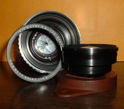
Carl Zeiss Jena Biometar 120mm f/2.8 This lens was part of a large group of cameras/lenses I fixed for a friend of mine, Uf Tureli. It was my first opportunity to tinker on a huge Kiev 6C medium format SLR as well as three various make lenses that fit it. He was brave enough to allow all these items to cross my work desk simultaneously. Thanks for the confidence Uf. Before starting I'd like to make a grandiose statement: All cameras and lenses are simple to take apart…if…if one knows how. Having said that, this lens was a very difficult adventure. It is not obvious how it comes apart. In fact the helix guide rail design is down right weird. But I'm getting ahead of myself. Looking back, it would have been easy…if…if I'd known how it came apart. But I didn't. By the time I learned the easy way, parts were scattered all over my desk. This is why I'm here…to hopefully save you a bunch of trouble by showing you the easy ways. So you can say, "Huh, that lens wasn't so hard." Usually all a lens needs is the aperture blades cleaned of oil that has weeped out of the helicoid grease. True enough this one needed that, as the blades were quite oily. But in addition two aperture blades had come loose and fallen out of their grooves. So this lens was going to have to be near totally disassembled.
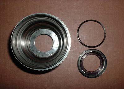
First thing that must be removed is the nameplate ring. It is the ring with all the lettering leaned against the lens body. There aren't any spanner slots so a suitable sized soft rubber piece must be found to unscrew the ring by friction. I used the lens cap of a large format lens shown in the picture to the left under the removed front element assembly. But any sink stopper or furniture foot cushion will work if it is the proper diameter. Luckily it wasn't very tight. The ring retaining the front glass kept wanting to unscrew first. Don't remove it unless you need to clean fungus or dust from between the elements. Always try to remove the elements as a group without separating the individual glass components. After the nameplate ring is off take a slot type lens spanner and remove the front element assembly. All screws and rings on this lens are right-handed. If all you need to do is clean oil off the blades, the rear element can be removed at this time with the same slot spanner. The hood screwed into the rear element may break loose first, but don't worry, go ahead remove it then unscrew the rear element with the same spanners. If it's a pain getting the loosened rear element out the tight fitting hole in the mount, just remove the four screws and lift off the mount. Nothing will fall out. After all glass has been removed, flush the blades with Ronsonol lighter fluid and let dry over night or carefully blow dry with low pressure. High pressure can harm the blades. The main reason to remove both sets of glass is to avoid the hassle of trying to clean the oil that was just flushed from the blades, but now is on the far element. Cleaning would have to be through the open aperture. If you don't mind this, only one element assembly need be removed. It doesn't matter, front or rear. But frankly, I always remove all glass. If you only needed to clean the blades, reassemble the glass and stop here.
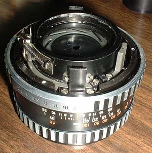
But, if you need to dig deeper, here is a picture showing the back of the lens with both the mount and the mount barrel removed. The barrel is removed by unscrewing the three inside screws. There is a thin cosmetic ring between the mount and the barrel. It'll mount backwards and give an incorrect register distance so study it before removing. Better yet mark it. While you are studying things, notice how the stopdown and aperture setting mechanism works. The stopdown mechanism is to the left (in the picture) of where the rear element screws in. It mounts with two screws and must be removed before splitting the helicoid. The only reason to split the helicoid is to clean and re-grease the helix threads. If your lens doesn't ABSOLUTELY need re-greasing don't put yourself through the torture of re-timing the helix to maintain infinity focus. But if it does, try unscrewing partway and applying moly-grease to the exposed threads first. Only split the helix if you really, really have to. But if you are masochistic, here is the way to split it: After removing the stopdown mechanism, remove the four screws and two gibs that restrain the inner helix from turning during focusing. One of the gib screws can be seen just above the upside down 16 on the aperture ring in the above picture. The black rail in the forefront of the above picture slides through the "C" shaped gib. The aperture ring is held on by a combination mounting screw/guide pin. The screw-head cannot be seen in the picture but the guide pin part of this screw can be seen in the base of the groove at the far right. The screw is the only screw on the outer perimeter of the aperture ring. Don't lose the detent ball under the aperture ring. The inner helix can now be unscrewed out the front. But first… Before splitting the inner and outer helix I measured the distance (with gib removed and focused to the infinity stop) from the top of the guide rail to the lens body. It measured .608" but your lens will undoubtedly be different. Some people like to scribe matching marks on the helix halves. The object is to get the multi-lead helix thread started in the correct thread. If you look closely at the threads you'll notice how a new thread starts every few degrees. One thread off; focus is off!
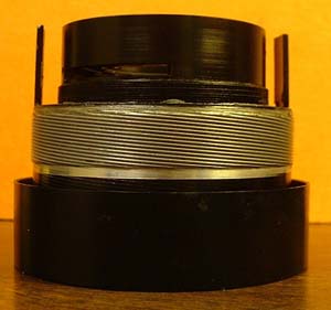
Here is the inner helix removed. The weird design mentioned earlier is how the black housing on top (that the rear element screwed into) is screwed and GLUED into the silver helix part in the middle. I never separated this joint for fear it might come loose later if the glue used wasn't strong enough. The torque of focusing is transmitted directly through this joint. Weird. If you don't split this joint (and I highly recommend that you don't) you'll have to get to the blades from the lens front with tweezers and probes. It really wasn't that difficult or tedious.
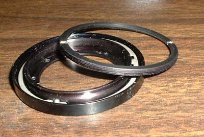
Looking in the front you can see two thin retaining rings. They can be seen in the first picture of this article. The outer ring holds in the aperture bearing race assembly, seen partly disassembled in the picture to the right. Remove the outer ring then lift out the aperture race assembly. The oily blades will stick the blades, race and base together. This sticking is what confused me to where I finally split the helix to see how everything goes together. I thought something else was holding the race in place. Hopefully with these pictures and description you'll be spared this "fun". Be careful pulling out the race as some of the blades are interwoven and may bend if forced. Also the stopdown lever must be extracted from the groove in the inner race. If it doesn't slip out easily, loosen the mounting screws to give more clearance. The inner retaining ring holds the aperture race together. It also sets the ball bearing clearance. It isn't screwed down tight; it is held in place by a drop of paint. This was the problem on the lens you see here. This inner ring had unscrewed allowing the blades to pop out of their guide grooves. In my ignorance of the way this lens comes apart I unscrewed both rings letting the race guts fall out. But my mistake is your good fortune. It took about an hour but I discovered a trick that makes the race's re-assembly easy. First assemble the outer housing, the ball separator, the inner race and the retaining ring. The retaining ring should be screwed in about a turn. Then place the three balls in position through the gap between the inner race and the retaining ring and carefully tighten the retaining ring until zero play yet no binding is felt when turning the inner race. Fix in place with a drop of paint on the threads.
To install the 8 blades, position the aperture ring to f/2.8 and install the blades as shown above. Do not touch the cleaned blades with fingers. Use only tweezers and a probe such as a crochet hook for positioning. It is hard to see by this low resolution picture but the teardrop shaped blades have the pointy tip of the teardrop pointing clockwise. Start laying the blades in any position going clockwise overlaying on top of the previous blade. Blade number 7's tip goes under blade number 1 and nearly half of blade number 8 goes under blade number 1. This is the interweaving mentioned earlier. There is a slot and two tabs on the blade side of the inner race. The slot is for the stopdown lever arm and the tabs determine the aperture's stroke. Position the slot on the inner race at the edge of the hole that the stopdown lever arm sticks into. Remove the stopdown spring so the lever is free to be positioned and not disrupt the blade position. Or just remove the entire stopdown lever assembly. The tab closest to the slot should just rest on the aperture stop. The aperture race fits over the positioned blades. Make sure all blade stubs are fitted into the inner races holes. Tighten the outer ring to secure the aperture race then reattach the stopdown spring. Then reassemble everything in reverse order. |