Tool for Assembling Aperture Blades
by John
The following information is on a vacuum machine (Bradvac) that I designed to make the assembly of aperature blades easier. I thought that other people who are interested in camera repair might find the idea of interest, and possibly want to build one for them selves. I have used the machine on numerous occasions, and find it indispensible. Previous to having built it, I found the tedious task of assembling aperature blades to be a bit like trying to build a card house in a force 9 gale!
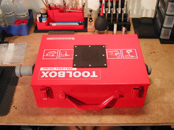
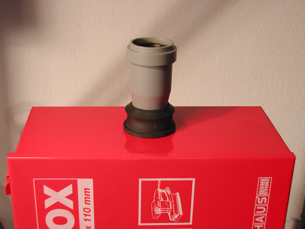
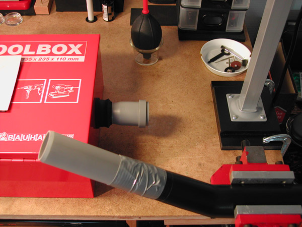
As per the images, the red metal box is designed to hold an electric drill, or similar tool. I chose it because it had some weight, a hinged lid, could be modified easily, and was cheap. It's dimensions are 13" long, 9 1/4" wide, and 4 1/2" high. After laying things out, I produced a round hole in each end by first chain drilling, and then filing to finish size. The square hole in the top for the vacuum pad was also produced by chain drilling, and filing. I recommend using a step drill, because it produces nice clean holes in thin materials, and gives you the advantage of several sizes in one bit.
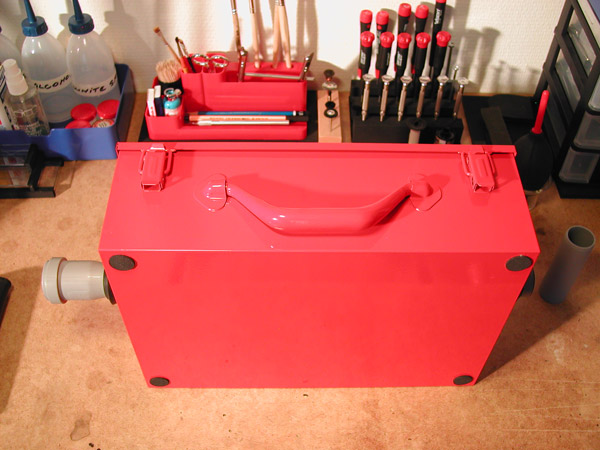
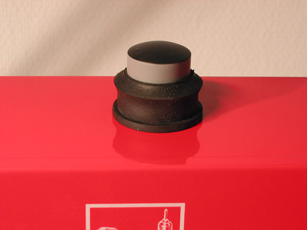
The gray vacuum tube is plastic plumbing pipe, and the rubber fittings are also associated plumbing parts. I ran the tube all the way through the box so that it would provide a rigid support for the vacuum cleaner hose. There are three rows of 5/16" holes, with each row having twelve holes. The holes were also made with the step drill, and then debured with an Exacto knife.
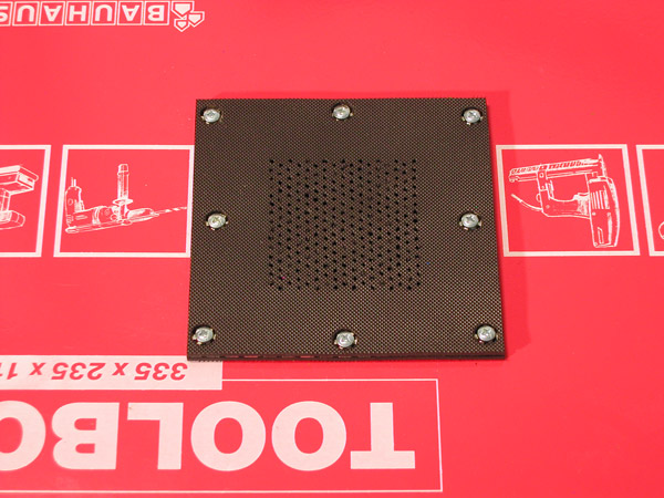
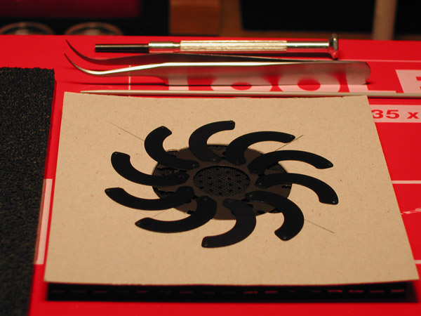
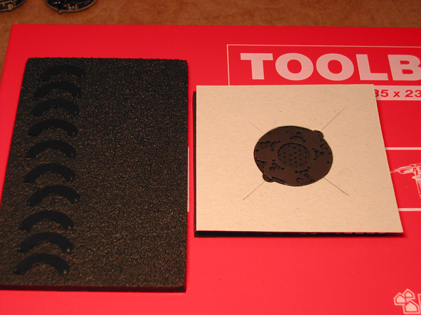
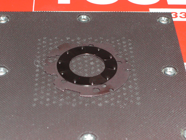
The black vacuum pad on the top of the box lid was constructed by cutting a piece of perforated aluminum to size with a hacksaw, bonding rubber to the top side with contact cement, and then turning the composite over so that the holes in the aluminum could be used as a drill guide for drilling the rubber. After the drilling was complete, I cut a rubber gasket to fit between the top of the box, and the laminated pad. This was bonded to the other side of the perforated aluminum. Before installing the top rubber, I had punched out holes where the attaching screws would enter the pad. This allowed the screws to sit flush with the top surface, and bear on the perforated aluminum underneath the rubber. The attachment holes were drilled last, and then the whole pad was clamped in position on the box, and the pre-drilled mounting holes in the pad used as a guide for drilling the mating holes in the box.
I had originally considered putting a gate valve on the outer end of the vacuum tube to control the vacuum. However, I decided it was not necessary as long as the vacuum cleaner received enough air to cool it's motor. In consideration of this necessity, I did not put a seal under the box lid, and found it unnecessary as initial tests showed there was more than enough vacuum to do the job. I judged the air flow restriction to the vacuum cleaner by the change in sound pitch the motor gave off as flow was gradually restricted.
The vacuum pad on top of the box could probably be simplified, but I wanted multiple small holes for obvious reasons, and a rubber working surface. Having said this, I'm sure the perforated aluminum would be fine on its own. Phonelic, or plastic perforated circuit board might also be a good choice if it was rigid enough. |