| Author |
Message |
    
L_n_h
Tinkerer
Username: L_n_h
Post Number: 1
Registered: 09-2007
Rating: N/A
Votes: 0 (Vote!) | | Posted on Monday, September 10, 2007 - 01:37 pm: | 


|
I have 2 Praktica MTL3 cameras which now have the same problem. After going halfway into the film, the picture is taken as normal, but the film wont wind on (the wind arm wont move more than 10 degrees or so). Pulling at the little lever top left of the mirror inside, whilst moving the wind arm did free the mechanism for a couple of times, but now this doesnt work either. The triangular 'signal' is still visible in viewfinder of both examples, so shutter not cocked. Needless to say it wont fire again until this is done.
In the 1st camera Ive pushed the button underneath, extracted the film, and the button stays pushed in (obviously that too wont come out again until the cycle is completed ie the wind lever fully operated). I have taken the top off following one article on this site, pulled forward the wind lock spring, which frees the wind-lock arm to turn all the way round. However doing this doesnt seem to solve anything, as in this disengaged state the usual mechanism of cogs etc is bypassed.
Can anyone suggest what I should be looking for/trying? My 2nd MTL3 has just developed the same fault, after exposure no.2, but Ive not attempted to rewind/extract the film, or even push the bottom button in yet -just in case someone can provide some timely advice.
Any help appreciated -they take nice pics, but I fear I may have to move onto a different make of SLR if this cant be resolved.
Thanks. l_n_h. |
Steve_s
Tinkerer
Username: Steve_s
Post Number: 52
Registered: 07-2006
Rating: N/A
Votes: 0 (Vote!) | | Posted on Tuesday, September 11, 2007 - 12:51 pm: |
|
There seems to be an epidemic of jammed Prakticas on this forum at the moment! I had a jammed MTL3 myself a few weeks ago. I spent ages peering and prodding in the mechanism. Eventually I noticed a screw-head deep inside where I was pretty sure no screw should be, and then noticed one of the screws holding the timing delay mechanism was missing from its usual home!
Have a good look around, but if you can't find anything obviously wrong the only solution may be to remove the timing mechanism so that you can see properly what is going on. It's best to take the timing mechanism off with the shutter cocked, but I guess it must be possible without. It's 2 or 3 years since I did it myself, but let us know if you want to try it and I will see if I can put together some basic instructions from notes I made. |
L_n_h
Tinkerer
Username: L_n_h
Post Number: 2
Registered: 09-2007
Rating: N/A
Votes: 0 (Vote!) | | Posted on Thursday, September 13, 2007 - 12:25 am: |
|
Thanks very much -yes Id love to try and have a go (the camera is as good as dead as it is now so theres nothing to lose). I cant see anything obviously loose, but it made a noise further down inside the works today -maybe nearer the button underneath-when I was fiddling with the stuff at the top. The bottom button hasnt come out again though and the thing is still jammed as before. But it sounded like something else has unjammed itself away from the area Ive exposed at the top. Look forward to your notes.
l_n_h. |
Steve_s
Tinkerer
Username: Steve_s
Post Number: 53
Registered: 07-2006
Rating: N/A
Votes: 0 (Vote!) | | Posted on Thursday, September 13, 2007 - 01:15 pm: |
|
The first thing to say is that on models with TTL metering like the MTL3 the shutter speed and film speed controls are linked to a variable resistance under the bottom cover. In the hole in the middle of the speed control is a taper headed screw which expands the split end of the spindle and locks it to the lever in the control which is normally linked to the film speed disc. This has to be freed before you can take the mechanism off, so set the shutter and film speed to one end of their range and note the position of the variable resistance so you can reassemble in the same position. Then just slacken the screw in the speed control and lift off the lever. I don't think this is an adjustment - the resistance just has to be in the right position relative to the speed control, so if you lose the setting you could get it back by comparing it with your other camera.
Detach the tiny tension spring from the frame-counter pawl (thread a bit of cotton through it first so it doesn't escape!) and remove pawl.
Remove the remaining frame-counter levers.
Remove the screw and lift off the frame counter dial, levering end of hair-spring off pin if necessary.
Cock the shutter (if you can) and remove 3 screws retaining shutter delay mechanism (one at the front and two at the back) and remove it.
When you put the delay mechanism back (with shutter cocked) push towards the right the lever nearest to the prism on the top brass plate so that it engages correctly under the plate.
When you reassemble the frame-counter, tension the hair-spring by one turn.
It's not too difficult, and hopefully you should be able to see something of what is going on. I hope this helps.
Best of luck! |
L_n_h
Tinkerer
Username: L_n_h
Post Number: 3
Registered: 09-2007
Rating: N/A
Votes: 0 (Vote!) | | Posted on Friday, September 14, 2007 - 07:54 am: |
|
Ok, Ive got the frame counter disc & hairspring off. But the shutter still wont cock, as the same old jamming problem occurs. Is there another way I can cock the shutter without using the lever column?
Also you say 'undo the delay mechanism via 3 screws: 1 at the front and 2 at the back'. Do you mean take off the big brass plate at the top? Please confirm.
Thanks. l_n_h |
Steve_s
Tinkerer
Username: Steve_s
Post Number: 54
Registered: 07-2006
Rating: N/A
Votes: 0 (Vote!) | | Posted on Friday, September 14, 2007 - 01:25 pm: |
|
Yes, the upper brass plate and the one below it and the gears between them will come off as a unit. This should enable you to see much more of the shutter-cocking and film-transport mechanism, which I hope might be useful. The shutter itself is cocked by a thin strip of springy metal which you will be able to see right at the back. It is pulled to the right as you turn the wind lever. I doubt if you can cock the shutter just by pulling it manually, but if it seems to move freely it might mean that the jam is somewhere between the wind lever and the hook that pulls the strip.
It is 2 or 3 years since I went there myself, so I am really just going by notes I made at the time, but if you do need to go any further in, I may be able to produce rough instructions. I had to change one of the gear wheels in the film transport, which meant I had to take most of the wind mechanism to bits!
You are remarkably unlucky to have 2 cameras with an identical problem. Normally they are pretty reliable, and the shutter (when you can cock it!) is very accurate. |
L_n_h
Tinkerer
Username: L_n_h
Post Number: 4
Registered: 09-2007
Rating: N/A
Votes: 0 (Vote!) | | Posted on Saturday, September 15, 2007 - 08:33 am: |
|
To answer your last comment first, perhaps it is unlucky, though these identical faults actually occurred a over year apart. The only other trouble Ive ever had with them in 20+ years has been shutters sticking closed when the camera accidentally got a bump in an upside down position; and that was soon solved by taking a photograph, winding on, then all was fine again.
Onto the subject in hand then:
I think you are narrowing it down. Brass plates off, and I note that when the wind mechanism is in full 'jam' position, the thin strip of metal which cocks the shutter will quite happily move to the right when pulled with pliars (it springs back when released). So its fairly certain the jam comes before the 'strip' movement. Furthermore I can now see a black metal lever which fits into a square groove in a disc attached to the film wind lever arm column -like a key (its interlocking with it at 3 O'clock, if you point the lens away from you). I dont know what this lever is, (it has a spring or wire on the front with a right angle turn which dives down into the front of the camera near where the shutter release button is), but the lever is meant to be in the disc at some stage of the cycle, as its a perfect fit. The disc+column cannot possibly turn with it in place. However there must be more to it, because this lever can be pushed forward and clear of the disc (and it will spring back by itself when released), but the disc+column still doesnt turn. You can see all the brass cogs below the column, and the mechanism up to the strip etc etc trying to move, then halting.
Other than this there no obvious other things to see. There are lots of cogs down there -it would only take one grain of dirt to jam that lot up.
Perhaps we should go onto the next stage... Im game if you are! |
L_n_h
Tinkerer
Username: L_n_h
Post Number: 5
Registered: 09-2007
Rating: N/A
Votes: 0 (Vote!) | | Posted on Saturday, September 15, 2007 - 08:58 am: |
|
Correction: that should be 9 0'clock that the lever interlocks with the disc, not 3 O'clock. l_n_h. |
Steve_s
Tinkerer
Username: Steve_s
Post Number: 55
Registered: 07-2006
Rating: N/A
Votes: 0 (Vote!) | | Posted on Saturday, September 15, 2007 - 12:53 pm: |
|
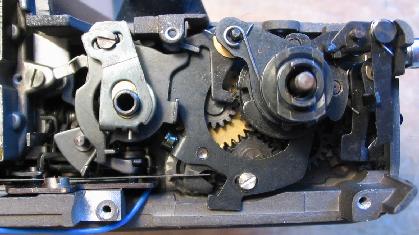
The lever you are referring to at 9 o'clock is the wind lock, which of course should not be in its notch unless the shutter is cocked. Is yours in the notch with the shutter un-cocked? I have a picture I took of the mechanism, and it looks as though this lever is operated by another lever below where the speed control normally sits. I would have a really good look around the area to see if you can work out how it is supposed to work, and why it doesn't, before going down any deeper.
In case it helps, here is the picture, which shows the mechanism in the uncocked position.
 |
L_n_h
Tinkerer
Username: L_n_h
Post Number: 6
Registered: 09-2007
Rating: N/A
Votes: 0 (Vote!) | | Posted on Tuesday, September 18, 2007 - 04:16 am: |
|
test message |
L_n_h
Tinkerer
Username: L_n_h
Post Number: 7
Registered: 09-2007
Rating: N/A
Votes: 0 (Vote!) | | Posted on Tuesday, September 18, 2007 - 04:33 am: |
|
Yes the wind lock is in the notch with shutter uncocked. By uncocked you mean the film has not been wound on after taking the pic? Yes I confirm: the wind arm never allowed the film to wind far enough I believe. The triangular 'flag' visible in the viewfinder seems to confirm this.
Thanks for pic -1st time Ive seen under the plates. By comparison, my camera's largest lever under the time control switch was in a totally different position to yours. The prong which should be pushing wind lock out of groove was by itself at 4 0'clock. After fiddling about I found the 'prong' lever was interlocked with another lever below it, which has a tag opposite the brass screwhead you see on the extreme left. Pushing this tag forward released the big lever, which sprang strongly into your pictured postition and freed out the wind lock. However, the wind shaft still wont turn, and the big lever when turned clockwise far enough will interlock with the lever underneath on the left to lock in the postion I found it again. The lever underneath has a hooked which doesnt seem to serve any other purpose than lock the big lever in place, as it just stands in 'mid-air' when the big lever is not attached to it. Other than see I see nothing different apart from the screw at the top of the area below the time switch is fastened down to the extreme left of the groove (yours in in the dead centre of it). Plus the shaft which holds the time switch and the tapered screw in the top wont come out (yours is removed in the pic). Does this suggest anything?
l_n_h |
Steve_s
Tinkerer
Username: Steve_s
Post Number: 56
Registered: 07-2006
Rating: N/A
Votes: 0 (Vote!) | | Posted on Wednesday, September 19, 2007 - 12:38 am: |
|
Since my last posting I decided it was time I tried to work out for myself just how these Prakticas work. They seem to have far more levers and interlocks than can be good for them! I took the delay mech. off my "scrap" PLC3 which had already had the front panel removed.
I have not considered the mechanism of the shutter itself, only the cocking mechanism on the top-plate, and the release/mirror mechanism on the front-plate.
SHUTTER COCKING MECHANISM: -
The pawl at 2 0'clock under the wind lever engages with one of 3 slots and turns the sleeve on the wind spindle anti-clockwise (all the gears are part of the film transport, nothing to do with the shutter).
The large complicated lever at 6 o'clock relative to the wind lever (I'll call it "A") is pulled to the right by one of 3 pins on the wind sleeve. Through a link, this turns clockwise a lever (I'll call it "B") which rotates round the speed control spindle. It is low down and not easy to see. It has a part at 8 o'clock bent down at 90� which I will mention later, and a vertical pin at 12 o'clock. The pin turns the big lever at the top under the speed control (I'll call it "C") which releases the wind-lock ready for it to fall into the next of 3 slots in the wind sleeve. Lever C continues to turn until it is caught by a latch, part of which sticks out horizontally below it at the top left. At the same time, lever A cocks the shutter by pulling a long flat strip at the back to the right, and levers A and B and the strip all then fall back to their start positions.
When the shutter is fired, lever C's latch is released (see below), lever C turns anti-clockwise and the pin sticking up on it pushes the curved lever at the left, which moves the longer of 2 vertical levers right at the back, which releases the first (lower) shutter blind. The upward tab on lever C then meets a lever on the delay mechanism which slows it down by an amount dependant on the speed setting. After the delay, part of lever C meets the shorter of the 2 vertical levers, which releases the second (upper) blind. Finally lever C lifts the wind-lock out of its notch ready to start the process again.
SHUTTER RELEASE: -
As the shutter is cocked, the part of lever B with the downward bend (right at the left of the cocking mechanism), moves forward pushing a vertical lever on the mechanism which is attached to the front plate until it latches in its forward position. This lever (I'll call it "D") is attached to 3 springs which are tensioned as it moves forward (It also has a slot in it in which the "tail" of the viewfinder cocked/uncocked indicator fits).
When the shutter release button is pressed, the centre of the 3 springs lifts the mirror, and at the same time the left-most of the springs pulls a lever rapidly forward, which releases the latch for lever C and starts the shutter firing operation. Finally, when the second blind releases, a pin on the shutter moves to the left, which operates a lever (pointing to the right, level with the back of the prism), which releases the latch on lever D, and the 3rd spring returns lever D to its start position and the mirror to its normal position.
This sequence is correct as far as I can see, but I'm open to correction.
Your lever C was obviously in the cocked position, and you have already found its release latch. The screw you mention in the slot at the top provides adjustment of the tension of the spring which returns lever C (there are also 2 options for the position of the tail of the spring) and this will alter the overall timing of the shutter speeds. If you have to dismantle anything here, make sure you mark this so you can put it back where you found it. The reason you can't see the centre spindle in the speed control (well spotted!) is that the photo is of an LB2, which doesn't have through-the-lens metering.
It seems as though you have now got everything on the top-plate into the uncocked position, and since you can see the tell-tale in the viewfinder, presumably your lever D is in the uncocked position. You can check this if you look down to the right of the prism. Just to the right of the prism mounting screw you will see a dog-leg lever which is the tail of the tell-tale. You will see that this fits in a slot in a lever, which is lever D. Uncocked, the top of this lever should be about mid-way betweem front and back of the camera. In its cocked position it will be right at the front, and hard to see. Its release latch is the lever you can see in the photo at the bottom left, just top left of the screw head (push it to the left).
All I can suggest is that you try to work through the system pushing and pulling things manually to see if you can find what is jammed. Check first that there isn't anything jamming the film transport gears, and that the pawl that engages with the wind-sleeve is correctly positioned (it can escape from its return spring when you are poking around down there). If you try to push lever D forward be VERY careful. Its springs are strong and when I tried it I broke off the rear corner at the top of the lever! It is quite easy to take the front plate off, by the way, but you do have to remove the covering.
I'm afraid it's all a lot of work for a camera that isn't worth much, but at least if you succeed you will get much more pleasure from using it in future than if it had never failed! |
L_n_h
Tinkerer
Username: L_n_h
Post Number: 8
Registered: 09-2007
Rating: N/A
Votes: 0 (Vote!) | | Posted on Thursday, September 20, 2007 - 10:17 am: |
|
Thanks for a super set of instuctions -even if I cant cure my camera problem there will be lots of others who will find these notes useful!
Your suggestion to check out film transport gears first would be my first thoughts too, as winding on was where the problem first becomes apparent. Most of the cogs seem free to move so far (even though meshed with each other, by turning the wind shaft, releasing the little 'bird-shaped' cog lock (on the extreme right back, near the opening mechanism), etc. However one cog that is very solid and wont budge is the one directly beneath the hook holding the end of the flat shutter-cocking strip. I note that this cog is directly above the reolving plastic, toothed column that takes the film inside the camera (with the metal push button under the camera beneath that). Whether or not this cog is meant to be stiff I dont know.
I can confirm that lever D was in correct uncocked position as you describe (ie in dead centre of camera rather than front). I did push it forward after unlocking the catch (not all the way forward as it was difficult to reach and I didnt want to force anything. Also I noticed that if the wind shaft was lifted very slightly, it could turn all the way round without having to pull the tiny lever that sits at 12 o'clock free of its retaining spring (the one I think you said 'make sure its held by the spring'). However I dont think this is a normal camera position when its put back together again, so I pushed the top of the shaft back down again the 2 or 3mm. Very soon after these 2 operations (unlocking & pushing lever D forward, and lifting the wind shaft slightly) I was aware of something loose rattling about inside. Eventually I took the lens off and located a screw, which was in the large space behind. This wasnt there before and I dont know where it came from: although it has a slightly thicker head, its about the same size & shape as the 2 screws that hold the 2 brass top plates at the back (unlike the front screw for the brass plates, which is different and a bit longer).
So unless Ive just accidentally undone this screw today by fiddling around, it may well be part of the problem. It could conceivably have been wedged by lever D somehow (which I cant see properly); or maybe whatever the screw held together has come apart and causes the jam. Perhaps even it might have damaged cog teeth somewhere. But whatever, the wind lever still wont turn. Nor do I see any obvious holes missing screws -apart from the six screwholes 3 on either side of the prism casing (not seen on your pic).
As its very hard to see all the workings from above Im very tempted to take off the front plate as you mention, to get a better look, and have peeled back the plastic casing to reveal the 4 screws either side of the lens area. But before I open it, are there any 'danger' points to watch out for? (Eg you say above that part of the shutter release mechanism is attached to the front plate).
Also Im wondering if there is anything to be done near the push button underneath, as I note the variable resistance is directly below the wind shaft area (admittedly this does sound like trying to run before you can walk!). Maybe one step at a time... |
Steve_s
Tinkerer
Username: Steve_s
Post Number: 57
Registered: 07-2006
Rating: N/A
Votes: 0 (Vote!) | | Posted on Friday, September 21, 2007 - 02:18 am: |
|
The gear above the sprocket-spindle should not be as stiff as you describe. Even if there was a jam elsewhere in the gears, I think you should be able to move it a little. On a working camera, if you open the back and rock the sprocket spindle to and fro, you should be able to get the take-up spool to move each way as well.
What you describe when you lift the wind-shaft is normal. The little circlip and its shims below the black disc on the wind lever stop this lifting when the camera is assembled.
The loose screw looks promising! I have had a good look round and can't see any screws with a thicker head (some with the same, and a few thinner), but it obviously came from somewhere. The 3 holes either side of the prism should be empty. I'm not sure what they are for.
Since you already have the body covering lifted, you might as well take off the front plate. It might show you the source of the loose screw, and also it would prove absolutely that the jam is in the wind/cocking mechanism on the top-plate. Just unsolder the 3 wires from the variable resistor (yellow and green and blue on mine) at the circuit board at the bottom. Undo the 4 countersunk screws at the edges of the front plate and lift it off complete with prism and mirror chamber. The circuit board comes with it, and I am 99% sure there is no other wiring to worry about on the MTL3 (though cameras with "electric" lenses are a little more complicated).
The wind/cocking mechanism and shutter work normally with the front off. You fire the shutter by releasing the latch for "lever C" at the top left corner. Assuming it is still jammed, it may be time to think about dismantling the wind/cocking mech. (if you want to go there!). Double-check that the gear above the sprocket spindle really is as tight as you thought, because I'd be reluctant to start dismantling here until you are pretty sure what is wrong. Once you start taking this mechanism to bits, you can't really tell if it is working until you put it back together! First of all, though, just in case removing the loose screw actually did release the jam, but there is now something set up wrongly to stop it working, make sure everything is back in the uncocked position, with all the latches released, and that it is really still totally jammed before you lumber yourself with a load more dismantling.
See what you can find when you have the front off, and if you want to start on the wind mech. I will post my notes. |
L_n_h
Tinkerer
Username: L_n_h
Post Number: 9
Registered: 09-2007
Rating: N/A
Votes: 0 (Vote!) | | Posted on Friday, September 21, 2007 - 10:05 am: |
|
Yes, front plate came off completely after desoldering a blue wire top left of prism -this must be another 'flash' connection. No vacant screwholes visible apart from one in the mirror chamber (bottom left, in the wall behind the mirror). But my other MTL3 has no screwhead here -at least not on the mirror side anyway...
From what can be seen, levers A-D seem to all work ok, though B is hard to check on. So Ive screwed the plate back on for now.
A couple of things worth noting. Firstly I found the shutter can be opened to the first stage by pressing very hard with thumbnail along the heel of lever A, as far as locking (and it has to be released by operating the 3-spring mechanism with lever D. This supports the jam being in the wind mechanism, as the pin that drives lever A never gets the chance to do its job.
Secondly, after taking off the front plate and revolving the sprocket spindle, I found the take-up spool is suddenly trying to turn freely, and the 2 black cogs directly above it feel much freer too. They cant go far as they are meshed with the other cogs, but its a big improvement. However the wind shaft now behaves erratically, as sometimes it wont budge the cogs nearest to it at all, and sometimes it will move them a little bit. Furthermore, the disc on the shaft has turned a degree or two anticlockwise since I pulled it up again and so now the wind lock will barely fit into the groove anymore (sometimes it doesnt fit in at all). I cant get the wind shaft to go back clockwise, but logically its not meant to go that way anyway.
The gear cog above the sprocket spindle doesnt seem to want to move much if at all. If I put a needle between the teeth and push, it sometimes gives a click and moves a miniscule amount, but no more. Maybe its simply a very good fit with the cog above so theres no tolerance, but I dont see much happening.
Im wondering if perhaps we've eliminated most of the mechanism as the culprit? There are still the cogs on top which may have something tiny like a speck of grit caught in them (lever A is covering half of them up), and theres a whole chamber which hasnt been looked into yet (ie down along the wind shaft and towards the push-button at the bottom. This wasnt revealed when I took the front off).
Nothing ventured, nothing gained. What do you think? |
Steve_s
Tinkerer
Username: Steve_s
Post Number: 58
Registered: 07-2006
Rating: N/A
Votes: 0 (Vote!) | | Posted on Saturday, September 22, 2007 - 12:54 am: |
|
If the take-up spool moved when you turned the sprocket spindle, then the gear above it must be free. It is not too easy to turn from above. I was pushing it with a screwdriver - I'm not sure you could turn it with a needle. There is not a lot of clearance between the teeth, but it would take something bigger than a bit of grit to jam them.
I am learning and relearning quite a bit as this thread progresses! I have just discovered that it is possible to remove the wind/cocking mechanism from the body complete. I'm not suggesting you do it, because if you have to do any dismantling, it will be easier with the thing still in place, but I can say that it does look rather unlikely that the gears themselves could be the cause of a jam, unless they were very badly damaged, and that there are no screws in the mechanism itself that could be the source of your loose one. BUT I have found one thing that looks like a very good source of both a jam-up and a loose screw.
The mechanism is held to the body at 3 points. At top right it is held by the pivot-post for the frame-counter levers. At bottom right it is held by a screw which you can see quite easily. At top left it is held by another screw which you can only see with "lever C" in its clockwise (cocked) position. Interestingly, this last one was quite loose on my camera (suggesting it may have a tendency to work loose), and when I took it out, it freed from its thread, but would not come out of its hole all the way because "lever B" was blocking it. In this position it was extremely easy to get the screw jammed under "lever B", which caused a solid lock-up of the mechanism, and it was very hard to free the screw. It only has a normal thickness head, but otherwise looks a good prospect. See if either of the screws is missing. If this was the cause of the original fault the question would be - why is it still not working, now the screw is free?
A couple of other things to look at:
When you lifted the wind spindle, the pawl below which turns the mechanism will have moved inward. When you pushed the spindle or lever back down, the pawl will not have engaged properly with its slots unless you lifted it a little as you did so.
While messing with the wind/cocking mechanism off the camera, I kept getting things out of sync or jammed up. I found that I could get back to the "start" position if I lifted the little pawl to the right of the wind spindle (about 4 o'clock), which engages with the gear wheel at the top of the take-up spool, and turned the take-up spool spindle anti-clockwise as far as it would go (as viewed from above) ie. against the ratchet, opposite to the normal direction of film take-up.
I'm still hoping you can find the cause of the fault before you have to do any more dismantling, because I am afraid that if you take it apart first there may not be anything obviously wrong! |
L_n_h
Tinkerer
Username: L_n_h
Post Number: 14
Registered: 09-2007
Rating: N/A
Votes: 0 (Vote!) | | Posted on Saturday, September 22, 2007 - 02:08 pm: |
|
The 2 screws you mention holding the mechanism are present and tight, but thanks for the suggestion.
Incidentally, the loose screw has only a slightly thicker head than the 2 back brass top plate screws. The difference is so small youd probably not notice if the screw was in place -you can therefore regard it as the same. (It is also marginally shorter too).
Today was a bit bizarre. Firstly I undid the front plate and separated it from the rest. Then tried to get the out-of-phase lever arm back in its groove by playing with the take up spool, sprocket spindle, pulling back the spool cog pawl etc, as you described. The disc + groove was still refusing to go back, and cogs not improving. I got frustated and removed completely the top of the wind shaft, which exposed the cogs better (only lever A was over them now). Tried carefully lifting the big wind shaft cog up and down a few times a tiny bit - careful not to lift it clear of its interlocking cog in case it wouldnt go back in place. Still no improvement, so I replaced the top of the wind shaft making sure the little pawl at 12 o'clock & its spring was out enough for it to fit back on properly (know what you mean about it can go too far in if youre not careful). Tried it all again: still out of sync, so put it down and picked up the other half of camera instead.
In the other half, noticed that 3-springed lever D mechanism was very loose at the top and until now assumed it was cheap workmanship, because when the shutter release button is pressed it forces the whole thing against the casing (so its not going anywhere -which I thought was normal). However on closer inspection I found 2 small screws (same size as the mystery one) to be loose -one right at the bottom holding down a long metal tab and one higher up also fixing the mech to the casing. Tightened those, now lever D doesnt wobble at all. (Theres also a much bigger screw right in the middle but this is OK). This made me wonder about the empty screwhole by the mirror base, which is very close to these other loose screws. The mystery one will fit in there, but its a bit tight as its head rubs against the end of another screw coming out from the other side. So I dont relly think it came from here (firstly it doesnt do anything there and if it was a tightish fit it would hardly work itself loose would it). So I took it out again. (Do advise if you have one there though -its at the bottom to the left, below lever D and in the wall below mirror level).
Those 2 loose screws was a bit of a surprise and shame on me for not spotting them earlier. So I put this half down and went back to the other half with the wind lever. And can you believe it, but the cogs ALL started turning at the first go on the sprocket spindle -not only that but the take up spool is moving at the same time! And the sprocket spindle gear is moving too as if its never been stuck. What made it suddenly unstick itself is unknown, and I wasnt even holding that part of the camera at the time. So Ive turned the disc just enough anticlockwise to enable the wind lock to fit into the groove perfectly, and left it at that. The disc will continue to turn much more anti-clockwise, but since thats not its proper direction Im hesitant to overdo it without your advice. But it wont go clockwise much more than the width of the wind lock -then it sticks. On top of that, the wind lock column is as troublesome as ever. If you try to turn that clockwise, all the gears immediately try to jam up again (even with the wind lock clear of the groove). So the old source of the problem seems to remain. (I tried to wind it earlier with the top of the shaft off, but no luck).
Whilst enjoying the freed cogs, the small button underneath the camera popped out. The base plate is off so the button fell out of the mechanism altogether. Ive kept pressing it in again (though you have to slide back a lever first which then catches on & holds the button in place. Im not quite sure whether this button is supposed to be in or out at this stage -its probably important as itll affect the cycle/sequence no doubt. The other new thing tried today was to move the resistance about back & forth inside its casing, pushing with a needlepoint, to see if that changed anything.
Also noted several more vacant screwholes in the front plate wall which would accomodate the mystery screw -but none have obvious need of one except as a physical barrier to block out light, since the only other light barrier just there would be the plastic casing and glue.
Are there any screws further down the wind shaft column, perhaps associated with the push button area? |
Steve_s
Tinkerer
Username: Steve_s
Post Number: 60
Registered: 07-2006
Rating: N/A
Votes: 0 (Vote!) | | Posted on Sunday, September 23, 2007 - 01:28 am: |
|
First, regarding the mystery screw and your front-plate assembly. The scrap camera I am working with is a PLC3 which had "electric" lens and a totally different metering system. Immediately below the 3 springs is a bracket holding a pair of electric contacts which I think must be part of the metering, and will not be on your MTL3. This bracket is fixed by a single screw forward of, and a little below, the lowest of the screws which I think are the ones you have tightened. Is this where your empty screw hole is? If so, it is not where the screw came from.
Everything in this camera seems to be held by 3 screws, and I noticed you have only tightened 2 of the screws holding the release assembly! Has your MTL3 got the self timer (not all have)? If so, take it off (3 screws, one hard to see under the 3 springs). Of course you need to take the lever off first if you haven't already (unscrew the outer sleeve with flats on it). Looking from the side, the 3rd screw for the release assembly should be at the top right, visible with lever D in the uncocked position. Is yours there?
Regarding the original problem, I wonder if it is possible that the loose screw WAS the cause of the original jam, and that current problems are due to something else. I don't think you have a problem with the position of the wind-lock. Don't forget that the wind-lock only has to fit in its notch when the shutter is cocked, and you haven't been there yet! You should not be able to get it near the disc if lever C is in its uncocked position. The wind-lock normally starts the wind/cock cycle aligned with a notch, but out of it. Turning the take-up backwards against the ratchet as I suggested last time, sets the wind-sleeve back so that the pawl which turns it when you wind is hard against the edge of its notch, and the disc is slightly clockwise of the wind-lock. You could turn the wind spool forward to line up the wind-lock in its normal start position. In any case, it will sort itself out as you continue to wind. Try to get everything back to their uncocked starting positions and start again. The gears are totally involved in film transport and cannot affect the relationship of the cocking mechanism components. Have another good look around and try to follow the sequence of events when you try to operate the wind-lever. Leave the rewind button out, as this is the normal working position. The variable resistance cannot affect anything, since it is uncoupled once you take the delay mechanism off.
Are you really certain it is the gears that are locking up? If so, maybe it is time to have a closer look, because as far as I can see it should be impossible for them to jam. You have already done the wind spindle. The speed control end is fairly self-explanatory, but be sure that you mark the position of the screw in its slot and which of 3 possible positions the short end of the spring (immediately below the spindle) is in. Disconnecting the shutter cocking strip is a bit fiddly. It helps if you pull the strip as far as you can to the right. This will be easier with the front-plate removed. I am very, very doubtful that the problem is in the gears, so try every other possibility first! |
Steve_s
Tinkerer
Username: Steve_s
Post Number: 61
Registered: 07-2006
Rating: N/A
Votes: 0 (Vote!) | | Posted on Sunday, September 23, 2007 - 03:18 am: |
|
I find you can just see the 3rd screw for the release meechanism without taking off the self-timer if you get the light in the right direction, so have a look first. It is just above a shiny spring. If you can't see it, it is probably not there! |
L_n_h
Tinkerer
Username: L_n_h
Post Number: 15
Registered: 09-2007
Rating: N/A
Votes: 0 (Vote!) | | Posted on Monday, September 24, 2007 - 06:22 am: |
|
Youve done it (twice)!
(I'll be brief as my mouse froze and I just lost a longer message.)
Firstly, the mystery screw fits into the 3rd hole -it only goed in crooked -even after 2 attempts and loosening the other 2 screws to give the whole mech some 1 or 2mm play. But it goes in, so I left it crooked as it seems tight (but you can see some thread on one side of the head!). I removed another screw holding down the mech to compare and they are identical. (Incidentally none of the faulty MTL3s have a self timer lever/mech). Maybe not the best repair, but at least its in.
Secondly, I put the manual wind lever back onto the top of the shaft and it turned all the way round! Yesterday I was only trying the wind shaft with fingers, which arent really enough force to work it. The manual lever didnt operate the shaft when the gear cogs were stuck, so the whole thing must have been ok once that happened (and of course the bottom push botton was out, as Id always had it pressed in).
So its a fair guess to say the initial fault was the loose screw jamming the mech somewhere, and once the cogs/spool/spindle got untangled it was 'all clear' as they say. Well done on getting me to this point -a great achievment!
Im starting to reassemble now. Slight delay caused by finding a pinhead sized spot of black paint missing on the prism edge. Quite clearly letting light in when its shone through camera front, so Im dabbing enamel model paint on to seal it. But it needs more than one coat, which takes time to dry.
Incidentally can you say if the blue wire which goes down left of the prism is for the light meter or flash? (as opposed to the blue+red pair which go down to the right of prism). This restricts access through the front plate. If its for the lightmeter I'll have to resolder it -if the flash it can be left undone. 2 reasons: I dont use flash (preferring B setting instead) and in case I need to go straight back inside the camera again, the less soldering the better, as my iron is too large & clumsy for the job. Im inclined to leave the flash wire/s undone permanently. |
L_n_h
Tinkerer
Username: L_n_h
Post Number: 16
Registered: 09-2007
Rating: N/A
Votes: 0 (Vote!) | | Posted on Monday, September 24, 2007 - 06:35 am: |
|
Ps One other question: on reassembling the bottom push button. Theres a sliding lever which holds it in place, and the button has to be pressed in for that to happen - otherwise the button just falls out when the bottom plate is off. When replacing the button and plate, should button be pushed under the lever or just lying loose over it please? |
Steve_s
Tinkerer
Username: Steve_s
Post Number: 62
Registered: 07-2006
Rating: N/A
Votes: 0 (Vote!) | | Posted on Monday, September 24, 2007 - 12:42 pm: |
|
Glad you got there!
I will reassemble my scrap camera now, so if you run into problems during assembly, post the question and I will try to answer while the procedure is fresh in my mind. I don't know if you took off all the frame-counter levers as I suggested in my 2nd post, but for the record, and for the benefit of anyone following this thread in the future, I see now it is only necessary to take off the disc/hair-spring and the top pawl in order to take the delay mech. off. The other levers only need to come off if you are taking the wind mechanism off, as I was when I made my original notes. I've a feeling that the lower lever, that resets the counter when you open the back, was a bit of a pig to get back with its spring! The lever you have to move to the right when you put the delay back is the one pivoted at the left rear corner of the top brass plate, and I think you want to do it with the shutter cocked.
I'm not certain about the wiring. I have taken the bottom off a MTL3 and there are 4 wires connected to the left-hand end of the circuit board. The centre two (brown) go, I think, to the photo-resistor, and the outer two (one red, one grey) go, I think, to the meter, but you won't have needed to disconnect these. Through the side of the mirror chamber on the left of the camera I can see the red and the grey wires and a blue wire, which I guess must go to the flash socket below the lens-mount. I can't see any wires on the right (apart from the 3 going from the board to the variable resistor).
When you refit the bottom cover, push the lever back against its spring and push the button right in so that the lever holds it in while you put the cover on. It will spring back out to its working position, of course, as soon as you wind.
Before you put the top cover back on, operate the shutter many times, until you are certain it really is fixed! I think the odds are pretty good (I hope!). When you stick the covering back on the front, double-sided tape is the best thing. A lot of glues will damage the vinyl.
Hope all goes well! |
Steve_s
Tinkerer
Username: Steve_s
Post Number: 63
Registered: 07-2006
Rating: N/A
Votes: 0 (Vote!) | | Posted on Tuesday, September 25, 2007 - 02:22 am: |
|
Something I missed last time round: When you are putting back the timing delay, the lever that fits on the split shaft in the timing control has to be in position in the delay mechanism as you do it. You can't get it on after the delay is fitted. |
L_n_h
Tinkerer
Username: L_n_h
Post Number: 17
Registered: 09-2007
Rating: N/A
Votes: 0 (Vote!) | | Posted on Tuesday, September 25, 2007 - 05:09 am: |
|
Ok thanks for these details -will watch out for them as we get on. And yes, I did take off the frame counter levers you mentioned.
However, theres a spot of bother at the moment. The film mechanism wound on ok and the camera shutter fired at the end of the wind -this was with the front plate off. But with the front plate back on the same happens -camera doesnt wait for the shutter release button to be pressed. Its supposed to wait for you to fire it.
I noticed that when the firing button is pushed, the tall vertical lever part of the shutter release mech (visible right at the top of the camera when the front plate is on) doesnt move forward like it did when I first opened it up. On taking plate off again and pushing forward lever D on the shutter release mech, it locks and then the pushbutton will move this vertical lever forward, like it originally did. Assuming that might be the correct position for the mech to be in, I tried to fit it back together like that. But theres only one problem -the release lever at the very back wont go to the left of the peg by the shutter cocking strip. You can of course pull it to the left, then the 2 camera halves fit together. But moving the release lever triggers the mech off and so the shutterbutton is inoperative again and the triangular flag is back.
So I seem to be in a situation where the shutter release mech is disengaged from the rest of the works.
I note the triangular flag does start to disappear from viewfinder when the front plate is on and wind mech is cocked, which shows lever D working ok; and all seems fine up to that point -but the shutter shouldnt immediately fire at the end of the wind should it? (Maybe it wont when the timer/delay is back on, but this still doesnt explain why I cant get the fire button to move the vertical lever forward, as it did before).
Sorry about this, its a pain I know...
(and Im having to put a third coat of enamel on that bare spot -it is getting darker, but the paint tends to run off or thin out on glass). |
Steve_s
Tinkerer
Username: Steve_s
Post Number: 64
Registered: 07-2006
Rating: N/A
Votes: 0 (Vote!) | | Posted on Tuesday, September 25, 2007 - 01:00 pm: |
|
I hope I don't have to try to figure out exactly how the release and mirror mechanism work! With the front plate off, if you push lever D to its forward, cocked position, pushing the long vertical lever forward (or pressing the release button) flips the mirror up, and pushing the lever behind to the left flips the mirror back down. If this happens, I don't think the problem is in the front-plate.
As for the shutter firing at the end of the wind stroke, this sounds as though lever C is not being held by its latch. Possibly something is wrong with the relationship between the levers on the front-plate and the body. Try to see why the long vertical lever doesn't move. There should be nothing in its way.
Are you trying to fit the front-plate with the shutter cocked? I just tried this myself, and I can't do it without releasing the cocking mechanism, so leave everything uncocked. There doesn't seem to be any trick to it - the front-plate should just drop in if you haven't fitted the delay mechanism (if you have, you just have to get the long vertical lever in its fore-and-aft slot in the brass plate). Its only the re-fitting of the delay mechanism where the shutter wants to be cocked (at least that is what I was told when I asked on this forum a couple of years ago, and it works for me!). I'm not sure which levers you mean by "the release lever at the very back wont go to the left of the peg by the shutter cocking strip". Did you dismantle any of the mechanism around lever C and lever B? If so make sure the levers are all arranged as in the photo.
All I can suggest is, make sure both the front-plate release mechanism and the wind/cocking mechanism on the body work OK when they are NOT united, then make sure everything is uncocked (lever D back, mirror down, lever C fully anti-clockwise etc) and try fitting the front-plate again!
Let us know how you get on. |
L_n_h
Tinkerer
Username: L_n_h
Post Number: 18
Registered: 09-2007
Rating: N/A
Votes: 0 (Vote!) | | Posted on Wednesday, September 26, 2007 - 08:00 am: |
|
Good news: You dont have to figure out exactly how the mirror/release mech works!
There were 2 problems at work. Firstly with the back half of the camera, the catch was indeed not hooking onto the lever C -thats why it fired upon winding. Dont know what was making it stick, but after moving it about, the mech worked well 1st time and the shutter stayed cocked when wound. Thanks for telling me where to look!
The second problem was in the front plate. The shutter release button was doing nothing unless lever D was cocked (in which case it moved the tall vertical lever forward) and pressing the lightmeter button raised the mirror, and even made it close again sometimes! Sorry about my attempt to describe what was happening -but yes, at one stage I was trying to fit the front plate on with the shutter cocked (to see if that would get the shutter button involved in the operation).
The cause found only after comparing the other 2 Prakticas: in the mirror area, bottom left at the front is a lever below a round pin. on this camera the lever was ABOVE the pin. This meant that the lightmeter button moved the pin (& so pushed up the shutter), when it should have left it alone. Hardly surprising the rest of the mech wouldnt work. The wrong position no doubt happened when I re-fastened down the mech with the mystery screw, as the mech was so loose it was hanging at an angle -plenty of room for the pin to get round the wrong side of the lever in the mirror chamber nextdoor. The parts have been readjusted (though the 'mystery screw' still insists on sitting in the hole crooked!) and Im reassembling the whole lot. Camera seems to work fine at the moment and next job is the awkward resoldering of the 3 circuitboard wires. (As you asked, no dismantling in the lever B or C area was done).
Again Im very grateful for your help and patience on getting me this far!
The counter disc is back on and associated levers in place and Ive given it one turn to tension it as you said. Noted that the disc sits at about exposure no. 22 when theres no tension on it, and obviously you have to set it manually to zero just before you put a film in. So will it automatically jump back 36 places when youve used up a film and open up the back? (Best to check now before the top is sealed again). Best wishes... |
Steve_s
Tinkerer
Username: Steve_s
Post Number: 65
Registered: 07-2006
Rating: N/A
Votes: 0 (Vote!) | | Posted on Wednesday, September 26, 2007 - 02:47 pm: |
|
Just to explain the workings of the frame counter: Immediately below the counter disc is the ratchet-wheel, with the 2 thin metal pawls engaged with it. The lower pawl is the one that pushes the frame-counter disc forward (clockwise) when you wind on. The upper one stops it dropping back. There is a stop on the ratchet-wheel which sticks out further than the teeth of the wheel. When you open the back of the camera the lever held by a little circlip, forward and to the right of the disc, moves outwards enough to lift the 2 pawls off the ratchet-wheel, but not far enough to lift them over the stop. The frame-counter disc turns anti-clockwise under spring tension until the stop hits the end of the pawls, which is the start position of the counter.
I agree that with zero spring tension the disc is at about 22. If you open the back of the camera and turn the disc clockwise you should feel/hear the pawls riding over the stop at about the start position of the disc, and if you let go, the disc will stay there in the start position until you close the back and wind/fire. Normally the counter will work in this position, but the reset when you open the back will be a bit weak. If you turn the disc another full turn clockwise (past the stop again) you should find that it increments and resets correctly, without the spring being overtightened at 36+ on the counter.
You don't have to do anything manually. If it doesn't work as above, check that the reset lever (the one with the circlip) is working properly. This is the one I mentioned previously as being a little bit awkward getting its spring fitted, though this time round I didn't find it as difficult as I remember! |
L_n_h
Tinkerer
Username: L_n_h
Post Number: 19
Registered: 09-2007
Rating: N/A
Votes: 0 (Vote!) | | Posted on Friday, September 28, 2007 - 07:28 am: |
|
Its done. The camera is back together and all looks to be in order. The only thing to do now is test it with a film to see if its lightproof -which will take some time to use up the remaining 34 out of 36 exp of the film thats currently in the other jammed camera.
No doubt I'll start to have a go at fixing that one too (while this is still fresh in memory!), but with all your notes and this new-found experience, hopefully it'll be possible to do without sending you all these posts again...
These are quite 'rattly' pieces of equipment, and so I expect it'll likely be another mech with loose screw, but thats for later. Meanwhile, my thanks to you again for a fantastic rescue job -without your help I certainly wouldnt have managed it!
Very best wishes.
l_n_h. |
Steve_s
Tinkerer
Username: Steve_s
Post Number: 66
Registered: 07-2006
Rating: N/A
Votes: 0 (Vote!) | | Posted on Friday, September 28, 2007 - 12:51 pm: |
|
Well done! The next one will be a lot easier. Re. light-seals: ALL old Prakticas need the light seal at the hinge replacing, apart from some later cameras (1980s?) which use a higher density foam and some which use a velvety material. Everything else is normally OK. See: -
https://kyp.hauslendale.com/classics/forum/messages/2/10131.html |
L_n_h
Tinkerer
Username: L_n_h
Post Number: 20
Registered: 09-2007
Rating: N/A
Votes: 0 (Vote!) | | Posted on Saturday, September 29, 2007 - 08:28 am: |
|
OK, will check that out. The double-sided 'tape' in my drawer turned out to be d.s.-mounting tape, which is a bit like foam draught-excluder. It looked far too thick to stick the plastic backing onto the camera body as it would stick out too much; but it may be ideal for sealing the hinge area (after one sticky side has been cut off). Im also half-expecting the big round hole in the front plate (where the self-timer lever would have been fitted on) to pose a problem; but it will only be so if the plastic backing isnt fixed down around it 100% good. However, these are things which can only really be 'trial and errored'...
Thanks for the tip! |
Steve_s
Tinkerer
Username: Steve_s
Post Number: 67
Registered: 07-2006
Rating: N/A
Votes: 0 (Vote!) | | Posted on Saturday, September 29, 2007 - 01:01 pm: |
|
You want the sort of double-sided tape that has just a very thin transparent sheet between the layers of adhesive.
For the foam light-seal your best bet is one of Jon Goodman's $6 kits as endorsed in dozens of threads on this forum! He sells on eBay under the user-name "interslice". |
L_n_h
Tinkerer
Username: L_n_h
Post Number: 21
Registered: 09-2007
Rating: N/A
Votes: 0 (Vote!) | | Posted on Sunday, September 30, 2007 - 09:43 am: |
|
OK, thanks.
Today I had a go at the second faulty MTL3. Though the same model, there are some differences -eg its got imitation leather backing on the outside instead of the 'plastic with squares' kind. (Theres also a clamp inside by the prism, screwed to the mirror casing, so its either a slightly smaller prism or perhaps its aligned a bit to the left).
All went fine until I think I made the mistake of unscrewing the 3 brass plate screws off before unscrewing the central screw in the timer knob shaft. This was a careless error, admittedly, but I forgot to check the order it should have been done. By the time I realised, there was a whirring sound (like a spring unwinding), and I found I couldnt actually get the brass plates off!
The timer shaft central screw was tight at first, and I loosened it to try and remove the plates plus that little L-shaped lever that can only come off once the plates are lifted clear of the central shaft. But I soon found that that little screw in the end of the shaft wouldnt re-tighten the L-shaped lever again! Dont know if Id somehow disengaged this part of the mechanism, and tried for 2 or 3 hours before finally getting it to retighten the lever (it would usually retighten itself every time though, oddly enough, its just the lever remained completely slack). Noted that undoing this shaft screw whilst holding onto the cog at the bottom loosened the whole mechanism, but I didnt want to take it apart in case that was 'fatal'.
Needless to say, my target here was the 3-spring mechanism where our last mystery screw came from. So front plate came off, but all screws on this one were very tight. Not able to check all the levers, etc as much was well-hidden under the brass plates, but luckily, after a lot of fiddling, our mystery loose part popped out between the brass plates themselves -this time a screw 'collar' with groove in the top! (Like the one holding down the film rewind lever, but this one was only 3mm across). Spotted likely source, which was an upward-facing bare screw thread right on the top plate, about 3 O'clock from the timer knob mech. There is also a pin right above this with a small spring-end hanging down over where the collar fits over the screw.
Once this was back on, and hopefully the right setting was chosen for the resistor, everything looks promising for this camera too now. It works without jamming, and the shutter speeds sound about right. It was a bit of a nightmare trying to establish what was the correct resistor setting though, because it was slightly different to the other camera -perhaps the loose collar may have affected it (as its in the area of levers that move when shutter speed etc are altered).
Im just thankful the problem didnt require looking at the bits that were under the brass plates, as I would have been stumped!
The 2 most obvious questions that spring to mind are: firstly How do you get the brass plates off this one? The last MTL3 was easy. The plates on this one were very loose indeed once their screws were off -the only thing that seemed to hold them was the shaft of the timing mech. But it wouldnt come off.
And secondly, do all the MTL3s have exactly the same resistor setting? (Hope so, as Ive adjusted this camera to the setting of the previous camera -not the setting I found it on upon opening, which could be suspect). |
Steve_s
Tinkerer
Username: Steve_s
Post Number: 68
Registered: 07-2006
Rating: N/A
Votes: 0 (Vote!) | | Posted on Monday, October 01, 2007 - 02:33 am: |
|
You are right about the location of the slotted nut. I think the problem tightening the taper-screw and locking the L-shaped screw may have been that you had lifted the delay mechanism enough to disengage the gears at the top of the long spindle that links it to the resistor, so that the top spindle (with the split end) was turning freely.
I can't think of an obvious reason why the delay mechanism would not come off. The whirring sound was almost certainly the delay gears and escapement mechanism turning, so possibly the shutter was cocked on one of the slow speeds, but I can't see why this would be a problem.
Thinking again about my theory that the setting of the main variable resistance relative to the shutter-speed/film-speed control is probably the same on similar Prakticas, I would be inclined to change it to "possibly the same"! I would set it as you found it if you can, and if you don't have any reason to think it has been changed or has slipped. Compare the exposure values with another Praktica with the same type of metering (your first MTL3 if you set that back as it started) before you glue the scale back on. You should be able to alter the setting quite easily, if needed, with the camera fully assembled apart from the shutter-speed scale and the bottom cover. |
L_n_h
Tinkerer
Username: L_n_h
Post Number: 22
Registered: 09-2007
Rating: N/A
Votes: 0 (Vote!) | | Posted on Monday, October 01, 2007 - 12:31 pm: |
|
Ok thanks.
When I said that the L-shaped screw was in a different position to the other camera's when I opened it, it could be that the shutter speed had been altered by then.
Today I think the 2 MTL3s, at least, might indeed have the same resistor settings. Because when the L-shaped screw was finally fixed down and set the resistor in the 3 0'clock position as found on that camera (call it camera 2), I then turned the L-shape round so it was in the 4 o'clock position that camera 1 had. The resistor now showed exactly the same position as Id found it on opening up camera 1! So thats something anyway...
At the moment Ive resoldered the underneath of camera 2 but the top is still off, and its not been light-sealed yet. But I do note that the tapered screw and the central shaft on the timer are very loose indeed. Yes the L-shaped screw is held tightly enough, and the tapered screw wont tighten any more, but all these 3 components -the L, the tapered screw, and spindle- will rattle around their central axis. They cant go anywhere of course, but im wondering if maybe I should re-open camera 2 again by removing the front plate, and see if I can tighten it all up by holding onto the black cog underneath again whilst tightening the tapered screw. (On re-checking the shaft on camera 1, its very solid and nothing at all is loose. Yes its true that once the spring and that black metal 'divider' fastens its 2 prongs over the 'L', it cant rotate much by itself). Do you think this will be a wasted effort? (Maybe the shaft wont tighten more; I was so glad to get the taper screw to hold the L-screw that I didnt wait around after that! Perhaps a loose shaft is acceptable? Or maybe its just asking for trouble).
Finally, you mention 'compare the exposure values' -do you mean compare how the needle in the 2 viewfinders react on different 'f' settings? I could do this, but will have to swap the battery between the 2 MTL3s each time, as the MTL5's battery wont fit an MTL3! (its much smaller than a 625). |
Steve_s
Tinkerer
Username: Steve_s
Post Number: 69
Registered: 07-2006
Rating: N/A
Votes: 0 (Vote!) | | Posted on Tuesday, October 02, 2007 - 05:01 am: |
|
I assume you don't mean there is slack when you turn the L-shaped lever. Do you mean it moves up and down, or side to side? Side to side clearance would definitely be wrong, but I can't see how it would occur. There will be a bit of up and down play, but it shouldn't be excessive. I don't know how the top spindle, with the split end, is held, but I would guess there is a circlip which might be visible with the delay mechanism removed. Before you tighten the taper-headed screw you should push the L-shaped lever down as far as it will go onto the spindle, but I don't think it would affect vertical movement.
As for comparing exposure values, I meant, as you guessed, that you should check that you got the same settings for speed/f-number on the different cameras, when viewing identical subjects (eg. an evenly illuminated wall), though it should really be cameras with identical metering systems. I don't know the MTL5, or whether it uses the same system (a simple bridge circuit on the MTL3). If you have re-assembled both cameras the way you found them, and the resistor is in a similar position, I wouldn't worry. |
L_n_h
Tinkerer
Username: L_n_h
Post Number: 23
Registered: 09-2007
Rating: N/A
Votes: 0 (Vote!) | | Posted on Tuesday, October 02, 2007 - 08:04 am: |
|
The slack is present when you push the spindle/L-shaped lever as a unit. (Ie the L-lever is tightly attached to the spindle and isnt independent of it anymore, but they both together have the play). Perhaps I should have said the spindle has the slack because it moves within its shaft housing, and of course the L goes with it -sorry about that.
The play was both left to right and up and down, but Ive just about eliminated the up and down by following what you said (index finger under the cog at the bottom of the shaft, thumb on the L lever, press hard together, then tighten-that did it). The left to right movement is same as before, but its no more than about 1mm. (There is no sideways movement at all in the other camera, which was the reason for asking).
Maybe its good enough to still work OK anyway; I regret not noticing how much sideways play there was before it was altered -the looseness could have been there already of course (and the camera was working fine until the grooved nut came off).
The top part of the mech moves very slightly as well (ie the bit which has the slot which governs how far the L-lever can turn, though again its not by that much. This was a secondhand camera (as opposed to camera 1, which was bought new) so I dont know if its had much abuse or not.
Anyway, theres possibly not much that can be done to improve it, or indeed hopefully its not a big problem. If you agree, then I'll wrap it up and finish the lightproofing. (were getting there...). |
Steve_s
Tinkerer
Username: Steve_s
Post Number: 70
Registered: 07-2006
Rating: N/A
Votes: 0 (Vote!) | | Posted on Wednesday, October 03, 2007 - 01:56 am: |
|
There is a fair bit of slack at the L-shaped lever but it shouldn't be excessive. I've just taken the delay mech. off my scrap camera and the top shaft (with the split end) is held by a circlip at the point where there is an open hole on the LB2 mechanism photographed above. You should not need to hold the top shaft up from below in order to push the L-shaped lever down on to it. If you do, this circlip is missing. If you don't, then this circlip must be there, and the slack is normal. If you conclude that the circlip IS missing (and think you might be able to find one to replace it) it would be worth your while while the covers are off to whip the delay mech. off and fix it. There is just the circlip there - no washer. |
L_n_h
Tinkerer
Username: L_n_h
Post Number: 24
Registered: 09-2007
Rating: N/A
Votes: 0 (Vote!) | | Posted on Wednesday, October 03, 2007 - 03:12 pm: |
|
More good news. I managed to take off the delay mech -at last! Confirmed, the circlip is there; its only tiny, and on top of a small raised column, if thats the one you mean. Then the gear must have disengaged again as it took nearly another hour of tightening /untightening the taper-headed screw because the L-lever wouldnt fasten down. Got it in the end though, so thats that.
I did take off the front again because it does vitually eliminate up/down slack of the spindle when you press the bottom of the shaft, even though the circlip is there. Sideways slack the same, but not surprising when you see how floppy the spindle is (this is the first time Ive seen it uncovered). That all said, it may have a wobbly bit here and there, but it looks like this camera is good enough to do its old magic again, and many thanks for that.
Incidentally, if you were wondering why the brass plates wouldnt come off in the first place, it was because the tapered screw had opened out the spindle top into a mini 'funnel' shape -not immediately noticeable, but enough to prevent the L-lever passing over it, and so preventing the whole delay mech coming off. Once spotted, it was simple to prise up and off the L-lever with a screw driver, and remove the delay. Naturally it was impossible to replace the L as things were, so it was a case of removing tapered screw from spindle completely and gently squeeze the spindle top closed again with pliars. Then the L and mech went back over it no problem.
Because of this shaft tightening business, the front plate had to be put back with the delay mech already screwed down. Bit more fiddly, but done it a couple of times now, and on first impressions it looks OK enough. But when re-assembling, how can I be sure the extreme left hand lever on the top plate (that should be pressed to the right as you put it together) has engaged or not? Its not easy to tell unless theres a definite test. |
Steve_s
Tinkerer
Username: Steve_s
Post Number: 71
Registered: 07-2006
Rating: N/A
Votes: 0 (Vote!) | | Posted on Thursday, October 04, 2007 - 03:26 am: |
|
When you push the LH lever to the right, you are just getting it on the correct side of the vertical pin on "Lever C" (the pin that engages with the release catch) so that it doesn't stop the delay fitting properly. Once the delay is on, and if the cocking and firing is working, then you don't have to worry. I think the lever is something to do with the "B" setting, but I haven't investigated further.
Incidentally, I've found that when fitting the front-plate, as well as getting the vertical fore-and-aft lever in its slot in the top brass plate, it may be a good idea to make sure the left-right lever (the one that releases the mirror back to its normal position) is on the left of the pin on the shutter which releases it. Again, this will probably sort itself out once you cock and fire the shutter. |
L_n_h
Tinkerer
Username: L_n_h
Post Number: 25
Registered: 09-2007
Rating: N/A
Votes: 0 (Vote!) | | Posted on Thursday, October 04, 2007 - 12:41 pm: |
|
Ok, Ive put front plate back on and it seems to be cocking/firing properly. Yes, the lever at the back always goes left of the pin, I do make sure. I do note though that the timer mech often makes a slight buzzing noise when the camera is BEING cocked (set on the lower speeds only), ie the lever wound round to pull the film forward. I wasnt aware of this sound during cocking before -is that normal? When shutter button is pressed after cocking on these slower speeds the timer mech seems to work ok, with a constant buzz and gradual differences in duration on the different settings -which absolutely sounds normal. I had a look at the delay mech and its the little copper-coloured part at the back, right side that makes the noise as it rotates, both whilst cocking and after shutter release.
By comparison, camera 1 makes no buzzing sound at all on the slower speeds, even when the shutter is released! The lower shutter speed durations all sound identical and this is obviously not right. (Im not 100% sure now if it did when it was reassembled, but am reasonably sure it must have because it was tested for just that purpose, and this fault should have been such an obvious thing to notice). So tomorrow Im going to have to take the top off (again!) and have another look to try and see why the delay mech isnt operating. Bit of an annoyance and setback, but thats life... (Problems, problems. Im sorry if this is driving you mad as well).
The 'B' setting seems to work well on both cameras.
Unfortunately I cant use my fully working MTL5 camera for comparison of sounds/shutter duration time in this case, as theres a film in it. |
Aford
Tinkerer
Username: Aford
Post Number: 20
Registered: 03-2007
Rating: N/A
Votes: 0 (Vote!) | | Posted on Thursday, October 04, 2007 - 01:17 pm: |
|
I have just checked the slow speeds on my MTL 3 and I can confirm that there is a buzzing or gear whirring noise on speeds from 1/15 - 1sec as the film advance lever is moved to cock the shutter. So this is normal.
Regards - Alf |
L_n_h
Tinkerer
Username: L_n_h
Post Number: 26
Registered: 09-2007
Rating: N/A
Votes: 0 (Vote!) | | Posted on Friday, October 05, 2007 - 12:15 am: |
|
Thanks Alf. Thats good to know anyway! |
Steve_s
Tinkerer
Username: Steve_s
Post Number: 72
Registered: 07-2006
Rating: N/A
Votes: 0 (Vote!) | | Posted on Friday, October 05, 2007 - 01:38 am: |
|
It sounds as though the escapement rocker is not engaging with the star-wheel in the delay on camera 1. I had the same thing on my scrap PLC3. When you get the top off have a look at the RH end below the frame-counter. Between the brass plates is a spring which holds the rocker on to the star-wheel. If the upper tail of the spring is resting on a pillar deeper into the delay, then this is your problem. Compare it with your 2nd camera. You will need to hook the tail of the spring with a bit of thin wire and pull it out to fit on its lever. It is a bit strange because you have to push the tail downward to engage it with the lever which looks wrong, but is the only way it can work. |
Steve_s
Tinkerer
Username: Steve_s
Post Number: 73
Registered: 07-2006
Rating: N/A
Votes: 0 (Vote!) | | Posted on Friday, October 05, 2007 - 02:29 am: |
|
I've just located some pictures of another camera in a previous thread: -
https://kyp.hauslendale.com/classics/forum/messages/2/7346.html
This shows a different spring to the one in my PLC3. Mine does not have the bend in the tail, and it seems to want to fit on the little hooked lug low down at the front of the lever, which makes it fairly easy to dislodge. If yours is the type in the above thread it is less likely to be the cause of your fault, but as long as the delay gears turn when you cock the shutter the problem is still likely to be in the escapement/star-wheel area. |
L_n_h
Tinkerer
Username: L_n_h
Post Number: 27
Registered: 09-2007
Rating: N/A
Votes: 0 (Vote!) | | Posted on Friday, October 05, 2007 - 07:47 am: |
|
Yes, BOTH springs in these cameras seemed to be in the wrong place. (I hope we are talking about the same springs here, but both springs are the type you appear to have -ie the ends are simply long and straight with no bends at the end).
Interestingly, camera 2 (which did have the timer working) had the spring in exactly the same position as on the picture in that thread you gave me above. Ie it was on the outside of the little black lever, pushing in. This still allowed it to work, but there seemed a danger of it sliding off the top (eg if the camera had a bump), as apart from the tension there didnt seem much else to stop that happening. So I lifted it behind the lever and onto the little lug in front as you describe. The tension wasnt as great, but at least its got more chance of staying put.
On camera 1, the spring was indeed well behind the lever and doing nothing, and once it was put in place in the same location behind the lever, the timer worked just fine. Problem solved, and thanks once again for that!
Tip: Use a needle-threader to pull the spring-tail into place; these have very strong, thin wire which is securely and already looped, and make the job of re-fitting easier.
Ive reassembled both cameras again. Everything looks Ok now, apart from the timer knob on camera 2 (which had the disconnected timer shaft tapered screw problems). The very top section (ie the silver 'top plate' that holds the top screw with black filmspeed dial) seems to be standing slightly proud of the main collar. Normally the outer sleeve of this knob and the top are flush, and only alter when changing DIN settings. But this central part is higher than the rest, only by about one millimetre, no more. When you change DINs by lifting the sleeve, you can hear something click once slightly each time you lift up the outer sleeve to turn it. Maybe this is normal too. I cant think that anything is seriously wrong, but its a puzzle why the top isnt flush like the other cameras.
Yes I was careful to make sure that little raised spot on the divider above the spring was sitting in the slit of the DIN disc, and that the downward prongs of the divider were correctly located in the holes whilst the big spring was pressed, and the little downward lug on the silver 'top plate' was fitted in the hole on the top shaft, so cant imagine its those parts that are to blame. Also the L-shaped lever below appears low enough (maybe its the L-lever I can hear dropping back down into its tray when the DIN is changed, thats all). And maybe a certain amount of tolerance is allowed (we already know this camera's spindle is very wobbly), and its merely a bit worse for wear. It could be quite usable as it is now, Im guessing, and only a proper test using film will tell.
Fingers crossed, weve just about finished the job (hopefully). |
Steve_s
Tinkerer
Username: Steve_s
Post Number: 74
Registered: 07-2006
Rating: N/A
Votes: 0 (Vote!) | | Posted on Friday, October 05, 2007 - 01:03 pm: |
|
I think I may have steered you wrong here. The fact that your 2nd camera had its spring in the same place as pictured in the other thread got me worried, and I had another look at the spring on the PLC3, and in fact it does have the bend, as in the pictures. When I found it, it was out of place, and I could not see how it could have come off if it had been on the tall vertical part of the lever because the brass plate would stop it (I've tried it, and it seems impossible to dislodge accidentally), so I put it on the lug at the front of the lever, which does not seem to have any other function. The tail of the spring does not line up properly with this lug though, which bothered me.
Don't panic, though! I tried my camera on my shutter-tester with the spring in each position, and there was no difference at all in the timing. Also, I don't think there is much chance of the spring becoming dislodged from the lug. Perhaps both positions are options. If you haven't finally fitted the cover to camera 2, though, I would be inclined to put the spring back where it was.
Regarding the reassembly of the speed control, I used to have the same problem here. I think you need to have a good look at all the component parts, because there are quite a few things that have to interlock with each other. In particular, the patterned disc (the one the shutter-speed disc is glued to) has a tab which has to engage with the top of the speed control, which is very easy to miss. |
L_n_h
Tinkerer
Username: L_n_h
Post Number: 28
Registered: 09-2007
Rating: N/A
Votes: 0 (Vote!) | | Posted on Saturday, October 06, 2007 - 08:34 am: |
|
Yes, the top was back on, but Ive put the spring back. (It was a really good idea NOT to resolder the flash wires-its saved a lot of work!).
I was going in there anyway to check if the timer was actually screwed down far enough (one reason why perhaps the timer knob wasnt flush, since the whole housing may be raised too high, or so the theory went). However, an experiment disproved it. If you miss out the big spring, you can place the components on top of each other precisely and without struggling, and it was clear that the patterned disc (where the shutterspeed disc is glued to) was still proud of the outer sleeve. I concluded that it must be the patterned disc itself that has become even more dished than it already is- perhaps by overtight screwing. So I flattened it a little in the centre, taking care to let the projecting lug still do its job, and now the thing is flush again. I had a look to see if there was anything elsewhwere in the shaft area that may be lifting the mech a bit, but cant spot anything (though its a complex arrangement so it doesnt mean there is nothing wrong). However, the best way now is to just go ahead and test the camera/s in the field.
A couple of things worth noting. I was undoing the knob which holds down the film wind lever (using a pencil eraser as a friction screwdriver), when the plastic cover - a black disc in the centre -came off. Its glued on like the shutterspeed disc, but Ive never taken this cover off before as the whole knob screws off as a complete unit. Under this cover is a washer and circlip which would have fitted onto the top of the wind shaft. Naturally as the knob is screwed off, the shaft top sinks away, and these 2 items are left to rattle loose inside the knob. This seems like a bit of unnecessary gear, as each time the knob is screwed off via friction, these bits become displaced. However you can also uncrew the knob by taking off the cover, removing them off the shaft top, and THEN unscrewing the knob via two holes in the bottom, in which you can fit a pronged tool. This wont scratch the outside parts of the camera either. But be careful when replacing the circlip -it shot off when I did it and I was lucky to find it again four feet away by dragging a magnet across the carpet!
One other tip- when adding double-sided tape on the casing to lightproof the cameras. Both types of casing (ie the leatherette and 'with squares' type) are very hard to stick to the metal bodywork because the vinyl is far from flat. In my experience they just lifted off again minutes later (adding elastic bands didnt help). Best solution Ive found is to stick the double-sided tape over the whole of the camera body to be covered, then expose the sticky upper half of the tape, then instead of just trying to make the vinyl stick to that, add a layer of epoxy resin to the underneath of the vinyl first. The resin fills in all those depressions in the vinyl, so that when you press it down onto the tape, a solid, no-gap seal is made. You still need to put elastic bands round camera casing to hold it downwhile it dries, as well as small objects between the bands and the casing (whereever the covering wants to try to lift again up the most). But when its dry, you wont have any more problems. Just make sure you dont overdo the resin, and DONT get it in any screwholes -wipe any excess off before it hardens- as its very hard to remove when set. Then if you want to get back into your camera another time, you can just pull the tape off, and the casing should be nice and flat when its time to seal up again. |
Steve_s
Tinkerer
Username: Steve_s
Post Number: 75
Registered: 07-2006
Rating: N/A
Votes: 0 (Vote!) | | Posted on Saturday, October 06, 2007 - 12:54 pm: |
|
Surprised you managed to get the wind-lever screw off without taking off the black disc, circlip and shim/s! It does mean that you didn't follow the sometimes recommended procedure of picking the disc off with a needle, which unless you are very careful can make a mess of the disc. Someone in a recent thread recommended removing the disc by glueing something to it and pulling it off. I use a flat-headed copper rivet and a contact adhesive. I have a larger rivet for the shutter-speed disc on Prakticas without through-the-lens metering, which don't have the convenient film-speed gap to lever the disc off with. The glue softens up and cleans off very easily with lighter fuel.
I think the circlip and shim are to prevent the sleeve or bush that the wind lever is fixed to lifting far enough to cause problems (eg. disengaging the pawl that drives the wind mechanism), so you should make sure they are in place on both cameras.
Anyway, it looks like you're just about there now - well done! |
L_n_h
Tinkerer
Username: L_n_h
Post Number: 29
Registered: 09-2007
Rating: N/A
Votes: 0 (Vote!) | | Posted on Sunday, October 07, 2007 - 01:45 am: |
|
Thanks. And well done to you too for your help -as Ive said before, without your guidance this task would never have been attempted, let alone completed!
One last question, a very minor one, as its long been a feature on both cameras that Ive ignored, and its about the wind lever -which is appropriate.
After cocking, the levers go back most of the way by spring action, but then stick a bit just before the end. If you gently push them back towards their proper start position (ie continue the clockwise rotation), they unstick just before getting to the end and the spring action takes over once again and finishes the job. I know the handles do get worn eventually at the top where they fits over the shaft, and this will give them a bit of play. But whats the cause of them sticking? It seems like something else. (This is merely a cosmetic point I think, as their performance seems unaffected). |
Steve_s
Tinkerer
Username: Steve_s
Post Number: 76
Registered: 07-2006
Rating: N/A
Votes: 0 (Vote!) | | Posted on Sunday, October 07, 2007 - 12:00 pm: |
|
The wind levers always do stop a few degrees before the clockwise stop. I think it is probably just to make the lever handier if you are doing action photography and want to take another shot very quickly. |
L_n_h
Tinkerer
Username: L_n_h
Post Number: 30
Registered: 09-2007
Rating: N/A
Votes: 0 (Vote!) | | Posted on Monday, October 08, 2007 - 09:13 am: |
|
OK. Thanks once again for all your kind help!
l_n_h. |
Steve_s
Tinkerer
Username: Steve_s
Post Number: 107
Registered: 07-2006
Rating: N/A
Votes: 0 (Vote!) | | Posted on Wednesday, March 05, 2008 - 03:13 pm: |
|
Just in case anyone tries to use this thread as a guide to stripping their Praktica, I thought I had better add some amendments for the record: -
1. Removal and replacement of the delay mechanism are NOT easier with the shutter cocked. In fact both are better with it un-cocked! Replacing it is easier though, if you set the speed control to 1/1000 sec.
2. The slotted nut which was the cause of the jam-up in L_n_h's second camera holds a stud in an elongated hole which forms an adjustment which will affect the speed at 1/500 sec and 1/250 sec. I've since met 2 other cameras where this nut has been loose! The effect is normally that 1/500 is identical to 1/1000 and 1/250 is fast. To correct it you need to move the stud in its slot towards the speed control until 1/500 sec is correct.
3. To check the setting of the potentiometer under the bottom cover, first set the film speed to 20 DIN/80 ASA. This is the only value at which the metering is operative through the whole speed range from 1 sec to 1/1000 sec. Check if the potentiometer slider runs symmetrically to opposite ends of the track when you go from 1 sec to 1/1000 and back. If necessary, slacken the taper screw down the hole in the centre of the speed control and reposition the slider of the potentiometer.
Hope this is helpful to someone! |
Leesobing
Tinkerer
Username: Leesobing
Post Number: 2
Registered: 01-2008
Rating: N/A
Votes: 0 (Vote!) | | Posted on Thursday, June 12, 2008 - 09:56 pm: |
|
anyone has photo it is hard to understand only words |
Steve_s
Tinkerer
Username: Steve_s
Post Number: 125
Registered: 07-2006
Rating: N/A
Votes: 0 (Vote!) | | Posted on Friday, June 13, 2008 - 01:26 pm: |
|
I have been putting together some descriptions. They are not really ready for public consumption yet - some pictures are missing and some could be improved - but you can have a look and see if they help. At least they are shorter than this thread!
http://www.ydo.abelgratis.co.uk/praktica_disassembly.html
http://www.ydo.abelgratis.co.uk/praktica_cocking_firing.html |
Leesobing
Tinkerer
Username: Leesobing
Post Number: 4
Registered: 01-2008
Rating: N/A
Votes: 0 (Vote!) | | Posted on Friday, July 04, 2008 - 11:56 pm: |
|
it is very difficult, I guess i will giveup |
|