| Author |
Message |
    
Esphotos
Tinkerer
Username: Esphotos
Post Number: 1
Registered: 11-2008
Rating: N/A
Votes: 0 (Vote!) | | Posted on Monday, November 24, 2008 - 03:46 am: | 


|
Hello all,
First time poster.
Recently I have aquired a number of yashica electro 35 rangefinders in all sort of conditions. And I have repaired most problems like coroded battery chambers, wiring, cleaning, and light sealing.
One thing I cannot work out is the adjustment of rangefinders.
When I set the focus to infinity, the two imeges at a far end don't overlap.
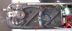
I have attached photo of camera in naked form. Can someone help me by marking which screw is the one used adjust the RF. And how to adjust?
Thank you
Edward
<img> |
Charlie
Tinkerer
Username: Charlie
Post Number: 185
Registered: 07-2006
Rating: N/A
Votes: 0 (Vote!) | | Posted on Monday, November 24, 2008 - 07:09 am: |
|
Do the pictures on this website help? |
Esphotos
Tinkerer
Username: Esphotos
Post Number: 2
Registered: 11-2008
Rating: N/A
Votes: 0 (Vote!) | | Posted on Monday, November 24, 2008 - 01:42 pm: |
|
Of course, where are they? Could you point me to the right direction?
Cheers
Edward |
Dirbel
Tinkerer
Username: Dirbel
Post Number: 11
Registered: 04-2008
Rating: N/A
Votes: 0 (Vote!) | | Posted on Monday, November 24, 2008 - 02:15 pm: |
|
You will find instructions to adjust infinity here:
http://www.yashica-guy.com/document/repair.html#six
Ciao,
Dirk |
Esphotos
Tinkerer
Username: Esphotos
Post Number: 3
Registered: 11-2008
Rating: N/A
Votes: 0 (Vote!) | | Posted on Tuesday, November 25, 2008 - 12:54 am: |
|
Dirk,
With all due respect, Yashica Guy's description is confusing and very hard to follow. In that article I could not even get which photo he was referring to. That's why I am here asking you guys to pin point me which screw I have to adjust.
Any one?
Cheers
Edward |
Msiegel
Tinkerer
Username: Msiegel
Post Number: 65
Registered: 03-2008
Rating: N/A
Votes: 0 (Vote!) | | Posted on Tuesday, November 25, 2008 - 02:29 am: |
|
From the description on the Yashica Guy website I would say the following:
The flash shoe has a covering plate which can be pulled. To do so you carefully lift it at the side where you can see written "ELECTRO 35" in the photo left to the description. On the top right side of the contact (one o'clock position)you see a black almost rectangular cutout. Through this the infinity screw should be accessible.
On the other picture mentioned in he text (the picture with the orange exacto knife visible) you see what's underneath the cutout in the top cover - namely a cover plate with an rectangular cutout. So guiding your screw driver through both "holes" makes it reach the adjusting screw.
The screw is not visible in the picture as it is underneath the hole. The golden (brass) coloured round thing visible on top of the contact seems to be a rivet holding the shoe to the top cover.
I cannot see the scotch taped screw driver which is mentioned in the text in the pic.
Note:
That is how I read the instructions on the website. I have never worked on a Electro 35 myself so someone with actual experience in doing so please correct me. But I think half removing the covering plate and having a look inside cannot do much harm. |
Charlie
Tinkerer
Username: Charlie
Post Number: 186
Registered: 07-2006
Rating: N/A
Votes: 0 (Vote!) | | Posted on Tuesday, November 25, 2008 - 06:42 am: |
|
I guess the reference didn't come up yesterday, I'll try again - http://personal.inet.fi/koti/picnet/electro/page_01.htm |
Esphotos
Tinkerer
Username: Esphotos
Post Number: 4
Registered: 11-2008
Rating: N/A
Votes: 0 (Vote!) | | Posted on Wednesday, November 26, 2008 - 03:26 am: |
|
Thank you Msiegel for explaining. I read a few times but still not getting it. It is written for experienced people, I guess. Anyway, I will have a go. It's $20 camera so I won't lose sleep over it if I stuff it up.
Thank you Charlie, I will study the pictures.
Cheers
Ed |
Msiegel
Tinkerer
Username: Msiegel
Post Number: 66
Registered: 03-2008
Rating: N/A
Votes: 0 (Vote!) | | Posted on Wednesday, November 26, 2008 - 04:29 am: |
|
Ed,
not wanting to use the pic from Yashica guy website I made a rough scetch to illustrate my posting (that's how I understand the text!!)
The scetch is based on what you see to the left of the descrition on the Yashica Guy website. |
Esphotos
Tinkerer
Username: Esphotos
Post Number: 5
Registered: 11-2008
Rating: N/A
Votes: 0 (Vote!) | | Posted on Thursday, November 27, 2008 - 03:33 am: |
|
Thank you Msiegel.
My problem is that I can't open the hot shoe. So it is easier to open the top cover. As you can see from the photo below, YG showed the screw being the one pointing by the second red line (bottom). But hot shoe slot is directly above the one indicated by blue circle. This screw is not turning.
Also, camera of this photo and the camera with RF cover shown in the YG's article are different cameras. And my camera is different to YG's. That's why I am getting frustrated.
Cheers
Ed |