| Author |
Message |
    
Aphototaker
Tinkerer
Username: Aphototaker
Post Number: 11
Registered: 12-2009
Rating: N/A
Votes: 0 (Vote!) | | Posted on Saturday, December 19, 2009 - 12:29 pm: | 


|
Hello,
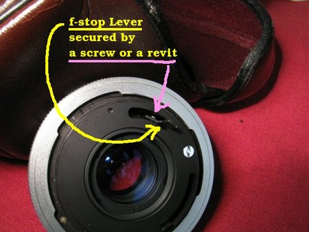
I have this 2x CPC teleconvertor for Canon fd lenses.
The lever that couples with the f-stop lever of the camera has grown some play in it, most likely due to a loose screw or rivet that secures that telenconvertor's lever to its body. The lever is shown in the attached image.
Does anybody have any suggestions on how to go about disassembling this teleconvertor to reach that screw/rivet?
I will try to post more photos the teleconvertor if that helps.
Thanks.
 |
Aphototaker
Tinkerer
Username: Aphototaker
Post Number: 12
Registered: 12-2009
Rating: N/A
Votes: 0 (Vote!) | | Posted on Saturday, December 19, 2009 - 12:38 pm: |
|
That was supposed to be "rivet" and not "revit". |
Glenn
Tinkerer
Username: Glenn
Post Number: 727
Registered: 07-2006
Rating: N/A
Votes: 0 (Vote!) | | Posted on Saturday, December 19, 2009 - 01:35 pm: |
|
Do not remove the optics - you will have to re-collimate if you do. Remove the stop screw from the breech ring and unscrew it, you may then be able to remove the rear shroud by unscrewing 3/4 radially located screws. I say may be because not all breech convertors are the same, on some models you have to go in from the front. In this instance remove the front mount, then remove the screws that hold the front baffle plate - the heads of these 2/3 screws face you as you look into the unit. You may then see some screw heads deep in the unit and these hold the rear mount, if removed the rear mechanism will come away.
As I mentioned the above is somewhat vague - I have no knowledge of your particular unit. However as long as you do not remove the optics, removing all visible screws will not produce any nasty surprises and will eventually expose the lever pivot. |
Aphototaker
Tinkerer
Username: Aphototaker
Post Number: 13
Registered: 12-2009
Rating: N/A
Votes: 0 (Vote!) | | Posted on Saturday, December 19, 2009 - 01:47 pm: |
|
What do you mean by removing the optics?
The teleconverter has a central cylinder which has the optics in it. I can rotate that cylinder. I realized that it should probably be at a particular position, so I rotated it back to the original place. Does this rotating also result in having to re-collemate the piece?
I will give the screws a shot. I did try to unscrew the lone screw on the breech lock ring, but that appeared to loosen nothing.
I was able to remove the front flange but could not see what to do further.
Having read your post though, I will take another look. Others, any hints?
Thanks. |
Aphototaker
Tinkerer
Username: Aphototaker
Post Number: 14
Registered: 12-2009
Rating: N/A
Votes: 0 (Vote!) | | Posted on Saturday, December 19, 2009 - 03:03 pm: |
|
Glenn, I took out the lone screw on the camera body coupling ring (shown in the photo in my first post in this thread), but that ring does not unscrew from the teleconverter body.
Also, removing the front metal ring of the teleconverter does not give me access to any screws.
The only screws I can make out are just below the camera body coupling ring at the back of the teleconverter. Only one is reachable without removing the ring (shown in the photo in the first post), the other three are partially under the ring.
The problem now appears to be just removing that ring at the back before I can do anything else.
Any further ideas?
Thanks. |
Glenn
Tinkerer
Username: Glenn
Post Number: 728
Registered: 07-2006
Rating: N/A
Votes: 0 (Vote!) | | Posted on Sunday, December 20, 2009 - 10:36 am: |
|
If you cannot turn the breech ring when the convertor is off the camera, then there is a detent that holds the ring in the remove position until the item is seated on the body mount. Look for a pin/plunger in the rear face of the unit that will be pushed by the camera mount as you attach the convertor. Release the detent and the breech ring will unscrew.
It is a very long time since I worked on a breech mount and the only lens I still have has been heavily modified on the mount - so unable to use as example. The pin/plunger should be situated on the rear mount face below the cutouts in the silver ring. Sorry that I cannot be more specific.
On the optical front - so long as you repositioned the cell to its original position you should have no problems. |
Aphototaker
Tinkerer
Username: Aphototaker
Post Number: 15
Registered: 12-2009
Rating: N/A
Votes: 0 (Vote!) | | Posted on Sunday, December 20, 2009 - 05:48 pm: |
|
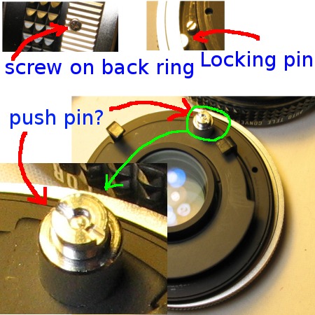
Glen, yes, you were exactly right. Thanks for the hint. There is a push pin that locks the rear coupling ring to the body of the teleconverter (tc). I have shown that locking pin the attached image.
Basically, I just remove the screw on the outside of the ring (shown in top left of the photo), then pushed the locking pin a bit to move the ring a little so that all three screws were accessible. Removing them brought the inner whole part (optics, levers, etc.) out of the black housing and I could also then unscrew the rear coupling ring (had to remove that tiny screw beside the locking pin as well).
Next, I noticed that the lever in question is still not accessible and to reach it I need to remove the black circular flange or plate. But this has a steel push pin in it which is preventing me from taking that circular flange out. The flange is screws by a thin ring, which was easy to unscrew.
I have shown the silver pin, and a blown up image of that pin, in the photo. That pin has a screw head on both sides and has a pin running through it. How do I take that push pin out?
 |
Glenn
Tinkerer
Username: Glenn
Post Number: 729
Registered: 07-2006
Rating: N/A
Votes: 0 (Vote!) | | Posted on Monday, December 21, 2009 - 12:25 pm: |
|
If both ends have driver slots then one end must come off, it will be a blind nut. Try a pair of screwdrivers and rotate very carefully. |
Aphototaker
Tinkerer
Username: Aphototaker
Post Number: 19
Registered: 12-2009
Rating: N/A
Votes: 0 (Vote!) | | Posted on Thursday, December 24, 2009 - 04:46 pm: |
|
Glenn, thanks a ton for your hints. Once that steel pin was taken out (one of the heads was unscrewed), the rest of the assembly was easy to disassemble to reach that lever's screws.
Once those screws were tightened and the converter reassembled, it worked like new! 
Warm regards. |
Glenn
Tinkerer
Username: Glenn
Post Number: 730
Registered: 07-2006
Rating: N/A
Votes: 0 (Vote!) | | Posted on Sunday, January 03, 2010 - 10:25 am: |
|
Glad it all worked out. |