| Author |
Message |
    
Tunashoes
Tinkerer
Username: Tunashoes
Post Number: 3
Registered: 03-2010
Rating: N/A
Votes: 0 (Vote!) | | Posted on Saturday, April 17, 2010 - 09:07 pm: | 


|
I am trying to get the meter to work on an AL-F. I have taken it apart and noticed that on the meter assembly on top there was only 1 black wire going to it. I don't know if this is right or wrong. It seems to be that there should be 2 wires a black and red, one coming from the CdS cell?? Does anyone have a wiring diagram? How do I get to the CdS cell? |
Tunashoes
Tinkerer
Username: Tunashoes
Post Number: 4
Registered: 03-2010
Rating: N/A
Votes: 0 (Vote!) | | Posted on Monday, April 19, 2010 - 07:43 pm: |
|
Well I confirmed that the meter works. I also measured the voltage going to the meter. I was indoors next to the window on a sunny day. The voltage seemed low, .040 or so volts. I noticed that the wire that comes from the CdS cell goes first through a potentiometer and then a resistor then to the meter. I wonder if anyone can comment on how a CdS cell dies? Do the go gradually, passing less and less current until they are gone? Or maybe I need to look at the pot and resitor?? |
Aphototaker
Tinkerer
Username: Aphototaker
Post Number: 201
Registered: 12-2009
Rating: N/A
Votes: 0 (Vote!) | | Posted on Monday, April 19, 2010 - 09:10 pm: |
|
One way to test the CdS is to measure its resistance at varying light levels. In dark, it should have a very high resistance (of the order of mega ohms). As you let light fall on it, its resistance should decrease (to orders of a few kilo ohms).
If the resistance does not change with varying light, the CdS could be bad or dead. |
Tunashoes
Tinkerer
Username: Tunashoes
Post Number: 5
Registered: 03-2010
Rating: N/A
Votes: 0 (Vote!) | | Posted on Tuesday, April 20, 2010 - 07:49 am: |
|
Thanks Aphototaker. I did another test for the CdS which leaves me to believe it is ok, I simply disconnected the wire from the CdS to the meter and with the battery in measured the voltage it was putting out at varying light levels, pointing it at a bright light I got a little over 1.35 volts and when I pointed the camera away from the light the voltage would drop, so that leads me to beleive that the CdS cell is operating as it should.
So I at this point I am confident that the CdS works, I am also confident that the meter works (via testing it with a AA battery).
All I can think is that the little PCB on the galvanometer may have been wired wrong???
There are two wires from the PCB going to the meter, a red and black one. On the meter is a pot and a resistor (a 15K ohm, which I replaced). The way it was wired when I opened it up for the first time was with the wire from the CdS cell going to the black wire of the meter and also on one leg of the pot, the circiut then when through the pot and then the resistor and then to the red wire to the meter. So that is what I am unsure about now, where does the +DC from the CdS cell go? (I apologize for my poor amatuer decriptions, I really need to take pictures to help explain what I am trying to say!) |
Aphototaker
Tinkerer
Username: Aphototaker
Post Number: 202
Registered: 12-2009
Rating: N/A
Votes: 0 (Vote!) | | Posted on Tuesday, April 20, 2010 - 11:45 am: |
|
Yes, pictures would be nice.
I am not familiar with this camera, so the following may not apply to yours. One common method of implementing CdS based meters was to have the battery, the photo-resistor (CdS cell), a potentiometer and the ammeter in series. The positive terminal of the battery is usually the system ground and connected to the chassis (metal body).
The pot is used to tweak the meter for calibration.
The battery check switch is just another circuit in parallel with the CdS cell and the potentiometer. With the battery check switch activated, the CdS and the pot (both) are disconnected and instead a fixed resistor is inserted, between the battery and the meter, that gives a predetermined deflection showing the battery level.
The CdS based circuit is pretty basic. Read the other thread here, titled "About CdS meters - some numbers, some..." by Marekle, which should explain this with more detail.
So, if you are not seeing a return path from a component, perhaps it is just the body.
Also, I am not sure I understand what you did by disconnecting the wire from the CdS to the meter. This should create an open circuit (unless I am missing something here) and you should get a fixed voltage (battery voltage).
Also, if you disconnected a wire from the CdS cell, you may as well measure its resistance. The circuit is open and no current is flowing and hence an ohm meter can be used. |
Tunashoes
Tinkerer
Username: Tunashoes
Post Number: 6
Registered: 03-2010
Rating: N/A
Votes: 0 (Vote!) | | Posted on Tuesday, April 20, 2010 - 02:23 pm: |
|
After rereading my statement "disconnected the wire from the CdS to the meter" it is misleading. I mean that I disconnected the meter from the wire going to the CdS cell (ie totally removed the meter from the camera). I have not disassembled the lens at all (that is were the cell is) so I don't have direct access to the cell itself.
Without the meter in the camera (but the battery in), I measured the voltage on the wire coming from the CdS cell (that goes to the meter, my assumption is the other terminal of the cell goes to the + battery) and used the camera body as ground. Doing that is when I measured over 1.35 volts to less than around .9 volts, depending on how I angled the camera (cell) to the light source. That leads me to believe that the CdS cell is working. ie voltage is present at the wire that feeds the meter.
You said "the battery, the photo-resistor (CdS cell), a potentiometer and the ammeter in series. The positive terminal of the battery is usually the system ground and connected to the chassis (metal body). "
I think this is basically how the AL-F works, except the negative terminal of the battery is connected to the camera body. And there is a fixed resistor after the pot.
Also, it seems to be very basic, there is no battery check or anything (that I am aware of).
It almost seems to me that the meter is not properly grounded. I would think the + voltage from the CdS cell should go into the pot, then the resistor then into the postive terminal of the meter and then the negative terminal of the meter should go to ground. But the way it is wired now, the "negative" terminal of the meter (black wire) is connected to the + voltage coming from the CdS cell and to the pot (that is in turn connected to the resistor that is in turn connected to the "positive" terminal on the meter (red wire). So it seems there is no ground present??? |
Aphototaker
Tinkerer
Username: Aphototaker
Post Number: 203
Registered: 12-2009
Rating: N/A
Votes: 0 (Vote!) | | Posted on Tuesday, April 20, 2010 - 03:25 pm: |
|
Since I am not familiar with this camera, and since no one else here has given any help to you, I believe the following thread on NelsonFoto should be useful to you:
http://nelsonfoto.com/SMF/index.php/topic,17120.0.html
I learned about NelsonFoto from somebody on this forum. Appears to be quite a nice forum. People appear to be knowledgeable and helpful, and, surprisingly,understanding and polite. You have to register as a user to see all the labeled photos on the URL I provided above. Apparently the guy brought back an AL-F to life and ended the thread by showing some photos he took with it. |
Tunashoes
Tinkerer
Username: Tunashoes
Post Number: 7
Registered: 03-2010
Rating: N/A
Votes: 0 (Vote!) | | Posted on Tuesday, April 20, 2010 - 07:49 pm: |
|
Thanks, I checked that out, good info. I guess he was lucky, only a spring needed fixed for the needle trap!!
Ok, I took a pic, here is the side of the meter housing with the PCB. The wire coming from the CdS cell was attached to the second contact from the bottom. The contact at the bottom has a red wire going to the meter and the next contact up has a black wire going to the meter. SO I guess I don't know if the meter correctly connected to the PCB or where the + V from the CdS cell should go or if there should be MORE wires!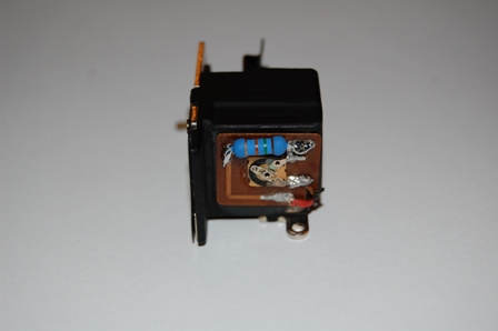 |
Aphototaker
Tinkerer
Username: Aphototaker
Post Number: 204
Registered: 12-2009
Rating: N/A
Votes: 0 (Vote!) | | Posted on Tuesday, April 20, 2010 - 09:09 pm: |
|
Okay, I checked the manual for Minolta AL-F. The way the battery is supposed to be installed in it, the chassis becomes ground and is at +1.35 V (or whatever battery you are using).
From your picture, it appears that the resistor bands (from left to right, as you have shown) are Black, Green and Brown (the last one appears to be golden, but ignore that). Is that correct?
Also, assume that the meter's metal contact with the chassis is the return path of the current (unless you can prove otherwise).
Let's call that blue resistor as Rf (fixed resistance) and that pot as Rv (variable resistance). Then, with the battery removed, can you use a continuity tester to verify what circuit you have?
Also, it would be better to actually draw the circuit as you understand it. I am attaching a figure for you with various components and labeled terminals. Either you edit that photo and draw the lines to show connections that you can verify, or just describe here which terminal is connected to which one.
One final question, why did you replace Rf?
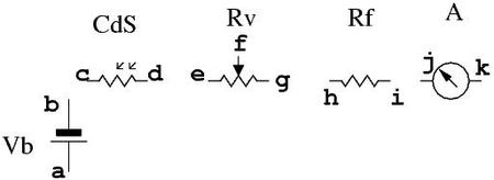
Vb: Battery
CdS: the photo cell
Rv: potentiometer
Rf: fixed resistance
A: ammeter |
Aphototaker
Tinkerer
Username: Aphototaker
Post Number: 205
Registered: 12-2009
Rating: N/A
Votes: 0 (Vote!) | | Posted on Tuesday, April 20, 2010 - 09:15 pm: |
|
Another little point, I usually take photos in similar situations by putting my digital camera in macro mode. This way I can focus on close distances and fill the photo with the subject I am interested in. Last, but the not the least, it also helps me to show the subject in a magnified form and thus easy to interpret and understand. |
Tunashoes
Tinkerer
Username: Tunashoes
Post Number: 8
Registered: 03-2010
Rating: N/A
Votes: 0 (Vote!) | | Posted on Wednesday, April 21, 2010 - 07:02 am: |
|
Thanks for all your help Aphototaker! This is only the second camera I have ever worked on so I am totally new to this (and photography in general)
Well the resistor was brown green orange, 15K ohm, I replaced it because on the orginal I was only measuring 7k or so. BUT it probably was a misreading, I probably didn't need to replace it.
This is embarrassing, but I really need to learn to use the macro mode on my camera (Nikon D40). I need to pull out the manual.
OK, hope you are ready for this! You said
"The positive terminal of the battery is usually the system ground and connected to the chassis (metal body)."
DOH!!!!!!!!!!!!!!!!!!!!!!!!!!!!!!!!!!!!!!!!!!!!!
(I think you know what I did)
The meter works fine. |
Aphototaker
Tinkerer
Username: Aphototaker
Post Number: 206
Registered: 12-2009
Rating: N/A
Votes: 0 (Vote!) | | Posted on Wednesday, April 21, 2010 - 07:17 am: |
|
Glad to know it works now.
It would be great if you can verify the circuit as you have it now in your camera. I am intrigued since from your posts it is not clear to me if it is a simple series circuit. So could you just mentioned which nodes are connected to which ones in the figure I posted earlier? Let me start:
a-chassis |
Tunashoes
Tinkerer
Username: Tunashoes
Post Number: 9
Registered: 03-2010
Rating: N/A
Votes: 0 (Vote!) | | Posted on Wednesday, April 21, 2010 - 08:02 am: |
|
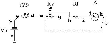
Your diagram looks right.
a-chassis is the battery +
Assuming, since I didn't take the CdS cell out, that B- goes to the CdS (b to c), then CdS to the pot (d to e) and also the meter (k in your diagram? black wire on meter so in your diagram e to k), then pot to R (g to h) then R to meter (i to j in your diagram? red wire on meter)
Also not sure since I didn't take it apart, there is the green wire for the flash.
This is what got me, I read the manual and it said when inserting the battery the positive side goes up, so I thought that meant up as in toward the TOP of the camera, INSTEAD of meaning when you hold the camera UPSIDE DOWN to put the battery in, put the battery positive side UP in an UPSIDE down camera! I guess it wasn't a problem with the orginal mercury battery since they would only fit one way, but with the 675 zinc air hearing aid battery and a rubber o-ring you can put the battery in RIGHT SIDE UP pretty easily! (DOH! DOH!)
(Oh and I guess I need a macro lense for my D40) |
Aphototaker
Tinkerer
Username: Aphototaker
Post Number: 207
Registered: 12-2009
Rating: N/A
Votes: 0 (Vote!) | | Posted on Wednesday, April 21, 2010 - 08:35 am: |
|
Thanks for the circuit description.
There seem to a couple of sticking points in the description, however.
1. From the pot, you probably meant f-h (since f node is the one that varies the resistance).
2. If you connected e-k, then the pot, the resistor and the meter are bypassed (they are not in the circuit anymore)! So that connection cannot be correct, shown by the dotted line in the diagram below (based on your desc.).
Also, I wrongly assume you were using a P&S digital camera. They usually have a macro mode built-in. Sorry, my bad. In your case, the minimum distance depends on the lens you have on the body. So if your lens is not a macro lens, the next best thing to do is to take a photo at maximum resolution, at whatever minimum distance you can, and then crop only the subject of interest. This usually works quite well. |
Tunashoes
Tinkerer
Username: Tunashoes
Post Number: 10
Registered: 03-2010
Rating: N/A
Votes: 0 (Vote!) | | Posted on Wednesday, April 21, 2010 - 12:47 pm: |
|
"From the pot, you probably meant f-h (since f node is the one that varies the resistance)"
That makes sense. I believe you are right.
This whole reversed polarity thing keeps me confused. It is hard for me to talk about ground and not mean negative! And then they scew with my head by having the red and black wires on the meter! (even the tab in the battery compartment that has a RED wire soldered to it goes to the NEGATIVE battery terminal!)
I know for certain that the black wire on the galvonmeter goes to one terminal on the pot and that the black wire coming from the down inside the camera (I assume the CdS cell) also connects to that same terminal. That same black wire is where I could measure voltage to "ground" the body.
Have a look here, same pic, only bigger http://www.flickr.com/photos/15294628@N06/4539658618/sizes/l/
I think you can see the details of the pot better. It looks to me to have only 2 leads, if that is possible???? |
Aphototaker
Tinkerer
Username: Aphototaker
Post Number: 208
Registered: 12-2009
Rating: N/A
Votes: 0 (Vote!) | | Posted on Wednesday, April 21, 2010 - 02:04 pm: |
|
Ground does not mean negative or positive. It just means a reference. But I see your confusion, since ground is commonly set to 0 V. In cameras, (as I have recently observed) the positive battery voltage is usually the ground, the reference. Everything else is with respect to this reference.
The red and black wires are most likely connected to the meter to show polarity for positive deflection. The meter is a simple ampere meter. If you switch its connections, the needle will try to deflect in the other direction.
Yes, the pot, the variable resistor, can have only two leads. In the picture you linked to, the effective resistance is between the lower lead of the pot and the upper lead of the pot. The upper lead is connected to a slider that moves along the circular resistive path. Rotating that slider changes the resistance between the two leads.
The way to trace out your circuit is two folds. You see where the wires go, and you can confirm the wire connections using a continuity tester (with the battery of the camera removed). Are you using a continuity tester? With a continuity tester it should be almost trivial to verify the diagram I showed earlier. |
David_nebenzahl
Tinkerer
Username: David_nebenzahl
Post Number: 279
Registered: 12-2009
Rating: N/A
Votes: 0 (Vote!) | | Posted on Thursday, April 22, 2010 - 03:21 pm: |
|
The reason that cameras have positive-ground electrical systems is simply because the cells that power them have their positive terminals at the outer, "shell" end, so it's easier to just let this terminal connect to ground (the metal body of the camera) through the battery holder.
I believe there were (are?) also some automobiles that had positive-ground electrical systems. |
Mndean
Tinkerer
Username: Mndean
Post Number: 223
Registered: 08-2007
Rating: N/A
Votes: 0 (Vote!) | | Posted on Thursday, April 22, 2010 - 09:28 pm: |
|
I believe that some British cars were positive-ground, ISTR the Ford Cortina (or one of the other models) as one. |
Tronds_63
Tinkerer
Username: Tronds_63
Post Number: 3
Registered: 12-2011
Rating: N/A
Votes: 0 (Vote!) | | Posted on Thursday, February 02, 2012 - 02:59 pm: |
|
Does anyone have any data for the CDS-cell?
What resistance does it have in darkness, and what resistance does it have in bright light?
I have a AL-F where the cell is broken. I measures about 17K in light and 41k in darkness, which is less than it should be. The meter needle never goes past 5.6 and selecting different shutter speeds makes the needle move about half a step for each step in shutter speed. |
|