| Author |
Message |
    
Josti_007
Tinkerer
Username: Josti_007
Post Number: 1
Registered: 02-2012
Rating: N/A
Votes: 0 (Vote!) | | Posted on Saturday, February 18, 2012 - 06:25 am: | 


|
hello everyone! i started the repair on a Minolta xd7. I'll briefly explain the problem:
The shutter was firing the same speed regardless what mode it was in (M, A or S). Also the battery was drained very quick though it was brand new.
I found a highly detailed repair manuals that helped me allot and got me the following information that confused me.
The troubleshooter in the back gives the following solutions to the problem:
1. "Electromagnet M3, open coil or not holding its armature. Check by shorting the brown wire to ground as you release the shutter. The shutter should stay open for as long as you hold the short. If not, the problem is with the shutter electromagnet M3." ----> this worked fine.
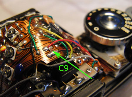
2. "Capacitor C9 (between brown and red magnet leads, Fig. 39) shorted." ----> I think that's the case.
If I check the electromagnet as in the paragraph i bump into the following: "If you measure the full 3V to the red wire and the brown wire, the switching transistor may be shorted." ----> this is the case.
Now I don't know if it's a capacitor or a transistor, but I wanted to start with the capacitor (It's the easiest to reach) but can't find any specification on capacitor C9. (also in attachment)
Maybe someone has experienced this problem or has some good advice. thank you for reading 
kind regards,
chris
 |
Michael_linn
Tinkerer
Username: Michael_linn
Post Number: 49
Registered: 04-2011
Rating: N/A
Votes: 0 (Vote!) | | Posted on Saturday, February 18, 2012 - 08:05 pm: |
|
Based on the symptoms you have posted, I would suspect H-IC. Check the voltage at pin 6 without touching the release button. If you get any voltage at all, the IC has an internal leak and is defective. That could be the cause of the battery drain. Also check pin 10 while releasing the shutter. You should get 3 volts at release. |
Josti_007
Tinkerer
Username: Josti_007
Post Number: 2
Registered: 02-2012
Rating: N/A
Votes: 0 (Vote!) | | Posted on Sunday, February 19, 2012 - 03:48 am: |
|
thank you for the tip! as i tried to remove the front-plate / mirror-cage, i found out that a person before me damaged the screws badly. it's almost impossible to disassemble the camera any further. I'll try to figure out the connections on the flexboard to try and measure the H-IC |
Thepurush
Tinkerer
Username: Thepurush
Post Number: 18
Registered: 01-2012
Rating: N/A
Votes: 0 (Vote!) | | Posted on Sunday, February 19, 2012 - 10:26 am: |
|
Remember to chceck firt evrything that you suspect without any dismantling too deep. Your problem surely is centerd abt shuuter magneet and the related circuite. I strongly recomend checking the circuite plate at the bottom where all magnet transistors are mountd. See figures 20, 21 and 22. There could be loose wires dangling ther. The brown wire must terminate on a well solderd terminal ther. also check evry solder jint ther for continuity between the components it joins. This is oftren the case. If you dismantle more, make sure u take photo of every thing so u can restore the wires to thier respective places. I glue the wire to the board abt 2 mm from solder joint so that even if i happen to remove thios circuite ther is no pisbility of wires coming loose from solderd joints. Suspect capacotor , transistor and the IC last. But your camera seems to hv been already mishandled, ther for ne thing is posible. |
Thepurush
Tinkerer
Username: Thepurush
Post Number: 19
Registered: 01-2012
Rating: N/A
Votes: 0 (Vote!) | | Posted on Sunday, February 19, 2012 - 10:31 am: |
|
If I check the electromagnet as in the paragraph i bump into the following: "If you measure the full 3V to the red wire and the brown wire, the switching transistor may be shorted." ----> this is the case.
But this may not be the case. What if the brown wire isnt solderd at the other end? Check at the bottom. |
Josti_007
Tinkerer
Username: Josti_007
Post Number: 3
Registered: 02-2012
Rating: N/A
Votes: 0 (Vote!) | | Posted on Sunday, February 19, 2012 - 03:29 pm: |
|
i meant that i measure 3V constant on the red and brown wire, therefore suspect a shorted transistor. do you know where to get these components to see if replacement is going to do the job? i could not find values or numbers that describe the capacitor (C9) or transistor (T6, T13). |
Thepurush
Tinkerer
Username: Thepurush
Post Number: 20
Registered: 01-2012
Rating: N/A
Votes: 0 (Vote!) | | Posted on Tuesday, February 21, 2012 - 05:20 am: |
|
First ans to your question: Capacitor C9 , the value is always availble on the part itself. But it has to be a high voltage type...atleast 1KV. But the capacittor works differently from the other capcotors C5 and C6 which are meant to discharge thru magnet coils. Where as C9 is ther only to absorb high voltage genrator when current stops flowing thru it. The trasistor in question should be only T12 alone and not T13 as you mentioned. Any switching transtor of SMD type that fit in place would be fine since the currents and voltages they handle are very small. If at all yout replaceing any of these I wd advise yout to take the hlep of some one who knows components well. But I see no reason to hurry up and replace ne of these. I explain below why.
To check T12 all you need to do is check continuity between batery plus and brown wire connected to electromagnet and terminal 8 of IC1 but WITHOUT battery in place. If it is a short then, Yes the trasistor is shorted.
Then you co fimed that when u tested the shutter with brown wire grounded it tested OK.
You had also mentioned that you get 3V on brown wire. This voltage also could be coming from terminal 10 of IC1. During the time when shutter is open this terminal should ground get grounded inorder to hold the shuuter open. This may not happen due to several reasons.
Firstly make sure that switch S7 open and close as it should. But it is always closed except breifly during shuuter operation. Fortunately thre is an easy way out. If S7 is always open the you wouldnt see the desplay of LEDs in the view finder at all. One way to check if it simopening breifly is this.
Put on lense cap and look in to view finder. Press shuuter half way and Concentrate on the led that is lit (choose mode M and a speed of 1 sec to 1000).release the shuuter, and u shd see the led go off brefly. If it doesnt then S7 isnt opening as it should. Also perform the same check in B mode, The LED shd stay on without a blink bcause now the s& isnt supposed to operate.
Then make sure that the trigger switch S4 is Ok , including the wire that connect it to the IC. See figure 39 of manual. With shutter uncokced the Black wire should have no continuity to ground. With shutter cokced it should be Shorted to ground. Check this at the solder land than on wire. Joints could be deciptive often. They look alright visually still the wires rnt connected to the soldered point.
If you find all this alright then the only posibliity could be the IC1 comparator is defective and isnt grounding the brown wire at all. I would still recomend that even before u do the above tests make sure that all connections are in place as they shd be, and the grounding is in order. Should you need more ssssitance I am availble at thePurush@gmail.com.
Good luck. |