| Author |
Message |
    
Bvandrasik
Tinkerer
Username: Bvandrasik
Post Number: 1
Registered: 03-2009
Rating: N/A
Votes: 0 (Vote!) | | Posted on Friday, March 06, 2009 - 11:05 pm: | 


|
I'm looking for some guidance on adjusting the RF of a Minolta HiMatic 7S. I took the top cover off to clean the internal glass, also removed the beam-splitter while cleaning to be sure I didn't accidentally damage the surface. On re-assembly, the vertical alignment appears to be way off. Did I mention this is my first attempted camera repair? (although I do have experience in clock repair)
Thanks! |
Nickon51
Tinkerer
Username: Nickon51
Post Number: 58
Registered: 05-2008
Rating: N/A
Votes: 0 (Vote!) | | Posted on Tuesday, March 10, 2009 - 05:23 pm: |
|
It shouldn't be "way" off. Some error is to be expected. I guess you have checked that it's up the right way?
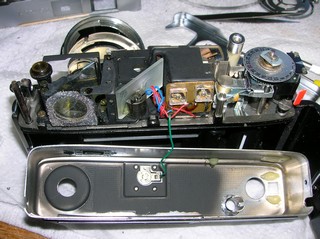
Here is a picture of the rangefinder. From memory the screws that you can see behind the first mirror, set the vertical alignment.
 |
Bvandrasik
Tinkerer
Username: Bvandrasik
Post Number: 2
Registered: 03-2009
Rating: N/A
Votes: 0 (Vote!) | | Posted on Wednesday, March 11, 2009 - 04:09 am: |
|
By "first mirror", do you mean the one on the right (not the beam splitter) ? |
Nickon51
Tinkerer
Username: Nickon51
Post Number: 59
Registered: 05-2008
Rating: N/A
Votes: 0 (Vote!) | | Posted on Wednesday, March 11, 2009 - 07:00 am: |
|
Yes that is the mirror that I was referring to.
I've taken a rangefinder out of a camera. I'm not sure now that the screws behind the first mirror are the right ones. I'll have another look at it tomorrow. |
Bvandrasik
Tinkerer
Username: Bvandrasik
Post Number: 3
Registered: 03-2009
Rating: N/A
Votes: 0 (Vote!) | | Posted on Thursday, March 12, 2009 - 04:09 am: |
|
OK, I figured this out. Forgive me if I do not use the proper part names, I'm new at this. There are 3 screws attaching the frame that supports the front element of the straight light path to the rangefinder assembly. I adjusted the outer 2 screws in equal amounts to bring the images into vertical alignment. |