|
|
| Favorite Classics |
|
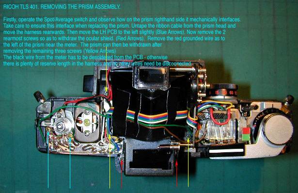
Ricoh TLS 401 This contribution is from a camera hobbyist who is has been often grateful for the articles of others on this forum. It is my way of putting something back into the forum in the hope that it will help someone. It simply focuses on two of the key issues peculiar to the model and which a reasonably competent owner might want to address in order to bring his TLS 401 into good working order. Lubrication techniques are beyond the scope of these notes and the practitioner is expected to be familiar with such. In brief: This is a heavy and very well engineered SLR as with a beautiful all-metal Copal Square shutter. For Spot and Average TTL metering Ricoh incorporated two independent Cds cells mounted on the reflex mirror. One for Spot metering as defined by the 12mm circle of the viewfinder screen - and one which reads the entire screen in "Average" mode. The camera top plate features a two position rotatable knob whereby one can choose between normal eye-level viewing or, through the top of the prism housing. This is not exactly "waist-level" viewing as it requires an eye proximity similar to the conventional eye-level viewing. But it can be useful. Ricoh calls this a "hollow prism" design . The fundamental problems: In my opinion, Ricoh went bananas in over-deploying cellular foam rubber buffering. We have a "hollow prism" which is really a box of mirrors with a hatch it is roof for waist-level viewing. The focusing screen is contained in its own carrier and is screwed to the "prism" to form an integrated unit. All of these joints - in addition to the interface of the ocular array, are buffered with self-adhesive cellular foam. In a camera of the TLS 401 vintage, that cellular foam will most certainly be crumbled. It will be all over the top surface of the focussing screen and inside the hollow prism. Thus the viewfinder image will doubtless be a grossly contaminated mess. There is also a battery wiring issue with the TLS 401. The Mercury Battery compartment tag is of stainless steel and cannot be soldered with resin core. The advantage is no verdigris corrosion. The disadvantage is that it must be soldered with plain solder and deploying a Zinc Chloride flux. Whether because of the original flux or whether because of the Mercury cell - the fact remains that the power supply wire is prone to black-wire corrosion whereby its copper core gets eaten away in an electro-chemical process. In this case the entire length of wire must be renewed.. Unfortunately that wire vanishes from the battery compartment up into the guts of the camera and terminates at a soldered tag on the left side of the mirror-box. These then are the service items which are the root of these notes. The
objective is to absolutely get rid of all any anything "cellular
foam"; render the camera incapable of any future similar contamination
and, lastly to renew the power supply wire so as hopefully to restore
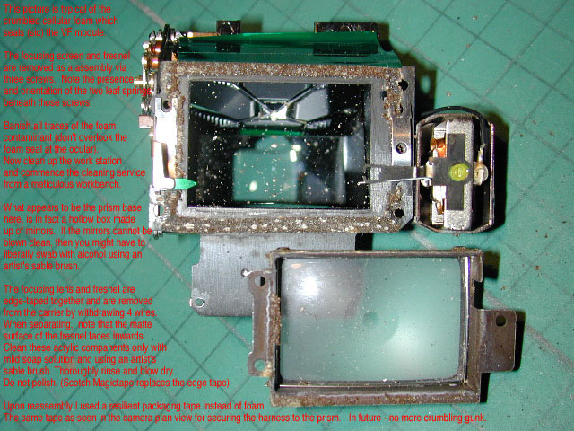
the metering to functionality. Removal of the camera top-plate is straight-forward. Then "wiggle" the top plate to free it and gently remove. About the focusing screen / fresnel. This is held in a carrier which in turn is attached to the prism base by three screws. Now here is an important modification if you are prepared to invest a little extra time to ensure that never again will your focusing screen get contaminated. The three aforementioned screws are also screwdriver slotted on the non-headed end and are over-length so that in "set-screw mode" they can be adjusted from above when the prism is refitted to the camera. The idea is that the focusing screen carrier is adjustable against two leaf springs so that the viewfinder focused image can be adjusted to correspond precisely with that on a ground glass film plane image to ensure the "Wot Yu See Is Wot Yu Get" However. Where there is such an adjustment, it follows there will be an air-gap path for debris to contaminate the focusing screen. So Ricoh used self-adhesive cellular foam strips to "take up the slack". Catch 22. Foam deteriorates and you are worse off bitten than chewed ! The answer is to use tape shims instead. Add and or subtract tape shims progressively whilst comparing the viewfinder focused image with that on ground glass at the film plane. Configure that the two correspond exactly when the focusing screen carrier is screwed firmly down, rock solid against its leaf springs. Thus there will be no pathway for any future debris contamination of the focusing screen top. Before doing this of course, you need to blow out and dust or bits from
inside the hollow prism and, if necessary, clean it. Same with the focussing
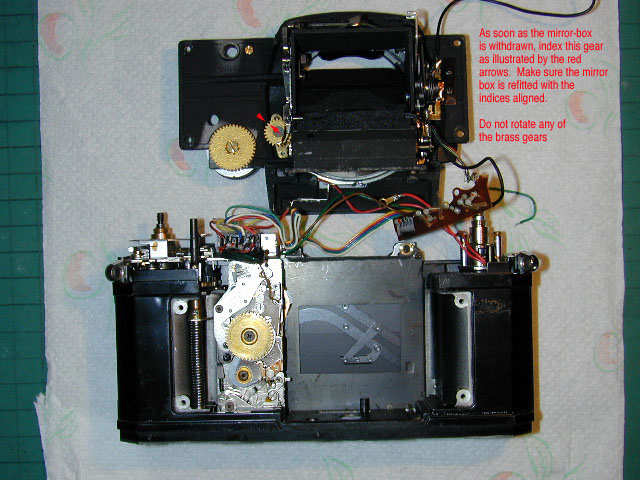
screen array. Replacing the battery wire. This requires removal of the mirror-box which can remain bridged to the main camera chassis by its wiring harness. There is no guarantee that renewing that wire will spark the metering into functionality but in my case is "was" so, Removal of the mirror-box is easier than on most SLR's. But there are also some serious trappings and care is needed when removing and refitting. Removing the leatherette from the two front panels reveals four screws which secure the mirror-box. Having already desoldered the battery compartment wire (or if it is in fact already severed or hanging by a couple of corroded strands), set the Self-Timer and return its lever to the vertical position. Set the shutter dial to some arbitrary speed (other that "B"), make a note of that speed, and do not henceforth disturb it. The timer is set in order to separate its internal activating arm from the pin which it drives. Thus upon refitting the mirror-box there will be no mechanical interference. Neither the shutter speed dial nor the self-timer lever are to be removed. This makes the job fairly simple. Remove the mirror box by lifting forward and diagonally upwards toward the camera top. The facilitates clearance of the timer arm which extends slightly into the camera chassis base. More particularly - moving the mirror-box diagonally upward toward the camera top, unmeshes the shutter and aperture-coupling brass gears. Be very careful at this stage. The mirror box can hinge on the wiring
harness and lay flat beside the camera on the benchtop. Do not disturb
the brass gears on the inside of the mirror-box. Use red nail varnish
spots to index them so that upon refitting they are in exactly the same
positions as when the mirror-box was removed. Great time to remove all contaminants, solder a new battery wire to the
contact on the film-rewind knob side of the mirror-box and, more particularly,
to clean the reflex mirror. The latter is an easy job since both the top
and bottom of the mirror box are now open path and can be flooded with
refined petroleum or alcohol and liberally swabbed with an artist's sable
brush. Refitting the mirror-box. Refer to my JPEG so that if mechanical interference is felt, you know how to shift it slightly to ensure correct meshing of the brass gears. Do not on any account be tempted to rotate the shutter dial slightly so as to feed in the mesh. If you do this, you will probably end up with the shutter dial index line falling half way between the marked shutter speeds. About the electronics. The Spot /Averaging switch on the top of the camera is an eight point soldering job and the space between the tags is very small indeed. Needs a fine instrument soldering iron. On my sample the connecting wires were grey and corroded at the solder points and they each broke away with slight pressure from a toothpick. It is also a good idea to use a little Electrolube on a toothpick to clean the seven switch contact points. Replace the mirror buffer with a 2mm sliver of cellular neoprene (wet-suit material). Clean out the camera-back light-traps and simply lay in black multiply knitting yarn of the polyester non-hairy variety. Finally - I include a JPEG of my finished TLS 401 which just a couple of days ago was a useless "junker" mess. Hope these notes are helpful to 401 users. We will never again see an era of camera engineering like this and I hope your TLS 401 will give you as many future years of impeccable serve as I intend to extract from mine. Stuart Willis
|
