|
|
| Favorite Classics |
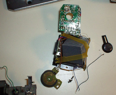
| Working on a Topcon RE200 by John Shriver These notes should apply equally to the RE200, RE300, and RM300. All of them are third-party cameras shipped with the Topcon name, among others. Looking at the front casting, it's obviously been adapted to the Topcon RE mount. I suspect it was indeed natively Pentax K mount. While it's a modest camera compared to the RE-Super or Super-D, with plastic parts, it is also more modern, and reasonably servicable. But I've never seen any sign of a service manual, I wouldn't want to have to calibrate the exposure meter. (There are at least 3 different trim-pots.) First thing, release the shutter. All the levers connecting parts of the camera disengage when the shutter is released. To remove the top, you will need to remove the rewind crank, shutter speed dial, and wind lever. The rewind crank comes apart in the ordinary way, put something through the slot in the bottom, and unscrew the top. Leave the shaft in the camera, you may need it to open the back. The shutter speed dial is held on by a small screw with two holes for a spanner. It isn't very tight, I was able to loosen it with tweezers. The shutter speed and ASA rings will pop off with a vigorous spring. You can then remove the outer ring, along with the Zamac casting inside it. All these parts are keyed, no problem putting them together. Don't remove the white gear, it requires particular alignment with the exposure meter. The cover on the wind lever has normal right hand threads, but they are tight, and no spanner holes are supplied. You will need to make or buy a circular wrench to remove it. I made one from some 2mm thick brass I had around. It's just a cover, under it is a screw. This lets you remove a washer, then the lever, then flat spring steel, and fianlly a Zamac casting. The top is now held on with two nuts around the wind and rewind shafts. Adjust a spanner wrench and remove them. When you lift off the top, the shutter button will fall out. The bottom is also easy to remove. Three flat-head screws. Watch out to not lose the rewind button, battery door, or battery door spring. The front trim is held on by the two flat-head screws, and the screw on the lens catch. Watch out for the spring behind the lens catch. When replacing, it goes in the recess in the plastic, not around the screw. The curved end faces the lens mount, the straight end pushes the pin on the catch. It's annoying to reassemble. If you want to remove the mirror box, you have to prepare for this. Make match marks with a Sharpie on the two white gears between the shutter/ASA dial and the resistor printed circuit board. Then pull the shutter/ASA gear, and unscrew the other gear. Remove the screws holding that PC board. Also remove the screws holding the circuit board around the rewind crank. A few wires will need to be unsoldered. Unsolder the black wire that goes into the body by the rewind crank, where it connects to the T-stop circuit board. Unsolder the two green ones to the hot-shoe spring contact. One goes to the shutter, the other to the PC connector on the front. The mirror box is readily separated from the main casting. You will need to temporarily remove the self-timer lever. Then peel the "leather" back 1-1/2 inches to expose two screws, and put the self-timer back together. Peel the leather back less on the other side to expose the other two screws. The stickum on the "leather" is very friendly, it can be reused quite a few times. Note that the four screws for the mirror box may have shims! Keep track of the shims if you find any. After pulling the screws, the mirror box comes off forwards. (You did remember to release the shutter first, right?) When putting the mirror box back, the only trick is that you will need to fiddle with the shutter interlock. It's a sliding lever on the bottom front of the mirror box, you need to slide it to get around the shutter button lever. Other than that, everything just fits together. You may need to fiddle the self-timer lever. The problems with my RE200 were twofold. The first was that the wind lever had been jammed when it was shipped to me after eBay purchase. The packing was so poor that it wasn't jammed when I received it. There's a pawl in the bottom of the camera that keeps the wind lever from going back until you've wound all the way. In mine, the pawl was bent, and the casting boss it pivots on was bent. I was able to flatten the pawl, straighten the casting, and file the surface of the casting smooth again. But this looks like a fiddly little lever, and I wouldn't be surprised if it's quite prone to jamming the camera. All it takes is a bit of oxidation or swelling of that Zamac casting. The second problem was that the exposure meter was doing nothing. My guess was that it was the switch that notes the shutter button being depressed. I was right. At first it looked like some idiot had repaired the camera before and used acid flux solder, several connections were corroded, and the bottom terminal of the power switch was severely corroded. I had to reinforce the bottom leaf of the power switch by soldering on a sliver of phosphor bronze. You have to remove the mirror box to unscrew the power switch. When I tried to resolder the connections, I found the real problem. The black wire used in this camera had defective insulation, which either contained a corrosive chemical, or decomposed to give off an acid. (PVC can generate Hydrochloric Acid pretty easily.) All the copper in this wire was corroded very black, brittle, and couldn't really be cleaned or tinned. It turns out that all the black wires are the negative power buss from the battery. (The camera uses a positive ground, the positive contact of the battery stack connects to the camera frame.) One wire goes from the battery to the T-stop ring circuit board, the other from there to the power switch. I replaced these with the leads from a grain-of-wheat bulb from the model railroad trade. The one to the battery has to be glued into two retaining notches with Pliobond.
I also pulled the prism. Not much reason to unless you want to clean the top of the focusing screen. Three pretty obvious screws, watch out for shims under them. (I had thought this was required to remove the mirror box, but it wasn't.)
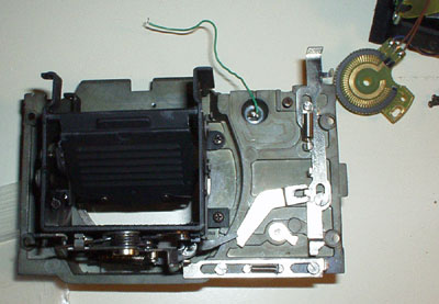
While I had the mirror box off, I replaced the mirror foam the easy way. I separated the mirror box proper from the front casting. Four very tight screws. Then I sprung the mirror box a little to remove the mirror assembly for safekeeping. This left it very easy to scrape the old foam with a wood stick, and apply new foam. Definitely the nicest way to do it on this camera.
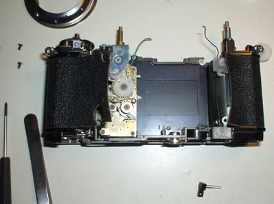
Remember I said not to separate the white gears for the shutter speed, at least without a match mark. The white gear is what sends the combined ASA/shutter speed information into the meter circuit. You would be wise to make a reference mark on both gear with a Sharpie as soon as you can. If you don't, it's not that hard to re-time. Set the variable resistor to the most counter-clockwise step before the contact goes off the end of the resistor segment. Set the shutter speed at 1/1000. Do many trial reassemblies of the shutter speed dial and ASA dial until ASA 25 at 1/1000 meshes the gears at this most counterclockwise resistor setting. (This is the voice of experience talking.) |