|
|
| Favorite Classics |
|
Yashica Lynx 5000 The problem with this camera is a broken pivot stub on an aperture blade. And another blade was rusty. The ONLY thing we need to do is replace these two blades. That makes it sound easy...so as to not frighten away the timid. In reality this is one of the most indepth things that can be done on this rangefinder camera. Nearly the whole lens will have to be disassembled. Everything except the shutter/self-timer clockwork and focus helix. In a previous article about recycling camera parts I mentioned trying to use the blades from the Copal in a Canonet QL17 Glll to fix this camera... they didn’t fit. But the correct blades were graciously donated by my good friend, and fellow camera tinkerer, Stuart Willis. Look for his repair articles on this webpage also. The parts came out of a Beauty Light-O-Matic 2, which is a 35mm rangefinder camera with a Copal SV shutter assembly, just like this Lynx. This proved my theory that parts can be interchanged between some camera makes. As with nearly every camera repair job the top cover must be removed first. Remove both screws from the sides of the cover. The rear screw is for rangefinder adjustment, leave it alone. As a side note: the other rangefinder adjustment is under the removable cover in the flash shoe. Next open the back and put a screwdriver between the tynes on the rewind shaft and loosen off the rewind knob. DON’T remove the screw under the flip-up twist handle. Just turn the rewind handle CCW with the tynes held. Use a pencil-point spanner to remove the wind lever. It is righthanded as is every screw you will encounter in this job. Lift the top cover off. Don’t bother with the bottom cover, it can stay put. Nothing under there needs removing.
Start at the lens and peel back the front leatherette until the four screws (two per side, see green arrows) in the lens mount plate are exposed. Remove these four screws and heat up your soldering iron. Four wires will need to be unsoldered: the blue, brown and red wires on the small resistor board mounted on the galvanometer and a black wire on the meter switch on the lens mount plate. You can leave the black sync wire soldered, it is long enough. Make a sketch of where the wires go before unsoldering. Separate lens and body. (When reassembling drop a drop or two of oil on the wind shaft (blue arrow). Nothing else in the clockworks need be lubricated.)
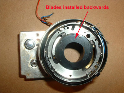
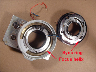
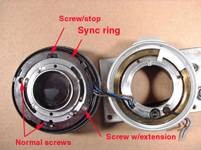
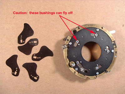
With a bladed spanner remove the rear element and the retaining ring under it. On this camera the retaining ring was so tight (even using acetone) I was afraid of breaking my spanner so I made a special tool from a thick bladed scraper. As you get deeper and deeper into camera repair you’ll start collecting several such special tools. Separate the focus helix from the rest of the lens. The wires will need to be pulled to give access but, if careful, can be left dangling. Remove the three large headed screws retaining the brass aperture adjustment ring. Then the single large headed screw retaining the flash sync ring. With needlenose pliers press out the pin in the wind shaft. Then remove the snapring on the wind shaft. This camera had two snaprings back to back. Next remove the four screws holding the clockwork assembly to the aperture housing. The screw with the funny head doubles as a stop and the silver screw has a long extention beyound the threads. Pull off the aperture housing. Caution the shutter blades may fall out and especially be cautious not to lose the tiny bushings on the shutter blade pivots. THEY ARE TINY. Refer to these photos: To get to the aperture blades remove the two screws and the retaining plate inside the housing. Make note of the direction the blades curve. My photo shows them reinstalled backwards. I did not realize I had taken a picture of them backwards until the lens was already reassembled. And I wasn’t going to disassemble it to snap a new pic! The trick to installing aperture blades is that the last blade you install slips under the first blade.
This goes to show the unwritten, but well known law, of the Taber workbench: Given two ways to assemble anything the incorrect way MUST be done first. Given several ways to be assembled ALL ways must be tried...several times. Ok, it is now written. Clean everything thoroughly with Ronsonol before reassembling. Don’t touch the blades or pieces contacting the blades with your fingers. Use twizzers and toothpicks. The salts and oils on fingers defeats the purpose of cleaning the blades. As an added feature, here is how to get to the clockwork. Remove the front element assembly as mentioned earlier. Then the three screws in the shutter speed dial. The shutter speed dial and the ring under it will now lift off.
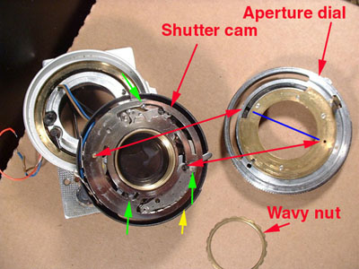
Turn the locking screw so the wavy nut can be unscrewed. This wavy nut is what sets the frictional drag of the shutter dial. It also controls the amount of play in the aperture dial/shutter dial joint. When reassembling only tighten until the drag feels right then lock with a half turn of the lock screw. Lift off the aperture dial. The shutter speed cam and detent lever will also lift off now. Putting the aperture dial back on can be a bugger. Especially if one (and yes I am the one) doesn’t study the pin locations before removing the cam. You know how you always read an explanation and the author says it is easier than it sounds... well, this ain’t! Install the detent spring/lever in the hole in the self-timer plate. Next install the shutter speed cam, with the side having the pin, up by slightly compressing the detent lever in the cam where all the notches are located and then slipping the cam on top of the clockwork. Turning the cam clockwise two other pins should snap into position. Three pins (counting the detent lever) are positioned in this cam. See the green arrows for pin locations. That’s the easy part...
Getting the aperture dial in place without dislodging the shutter speed cam is a bit trickier. Set aperture to widest opening (1.8) by rotating the aperture ring fully CCW with a thin screwdriver stuck in the gap shown with the yellow arrow. The lever on the aperture dial should be located in the groove of the brass aperture ring. Notice there are two pins that must locate into the aperture dial: the pin on the cam and a smaller one by the detent lever. The red arrows match pins to holes. They should be inline (180 degrees, blue line) when cam is set to “B” (fully CW, into the dropdown notch). The picture shows the cam in the 1 second position. It always takes me several tries...have patience. This is about as hard as it gets in Copal shuttered rangefinders. Are we still having fun? |


