|
Yashica Minister III Repair
by Stuart Willis
There are some cameras which are complex, difficult to service and which
one would not touch unless armed with a suitable technical manual. There
are other cameras which are known "lemons" - and a hundred technical
manuals won't change their status. The Yashica Minister III fits neither
category but it can be a tricky little workpiece if being tackled fairly
intuitively from one's past experience with popular priced rangefinders
of the 60' and 70's. If when I sleuthed a shutter problem on my particular
sample I had known what I know now, I could have saved myself lots of
frustration and unnecessary work. My purpose here therefore is to provide
for the guidance of others a short summary of key considerations - and
to support that summary with a few meaningful pictures.

Quick overview of the patient.
Coupled rangefinder. Non coupled meter as with selenium cell radial
around the front lens element.
Citizen shutter with full range of speeds 1/500 down to 1 sec., and B.
ƒ2.8 45mm Yashinon lens. The meter yields a Light Value which the
user transfers to the LV ring which is the forward ring aound the lens.
The shutter ring and LV ring are geared together so that either adjusts
when the other is changed. Ostensibly the shutter is a conventional 5
leaf design as with the foreward blade tip turned up a fraction. In fact
it has six leaves - the 6th being positioned exactly behind the front
leading blade but of course with the other four leaves sandwiched between.
I have no idea why Citizen included a sixth blade and its presence is
superfluous. More on this aspect later. Let's move on.
Purpose of my surgery.
Every camera tells a tale and my newly acquired Minister III spelled
it out its history loud and clear.
It came to me in near mint condition but with a non-functional shutter.
The camera told me that it had probably never taken a picture in its life.
It's shutter had jammed; someone had sought to address whatever the problem
by attempting to remove the top plate and succeeded only in butchering
the twin-hole key cap of the film advance lever-wind. The camera had then
obviously been chucked in some drawer or cupboard where it had lain for
decades.
Key factors.
The top plate is retained by a screw on each end; the film advance
leverwind and, the film rewind knob.
The latter simply unscrews in the conventional manner. The advance lever
cap is normally threaded (counter-clockwise to remove) but there seems
to be an endemic problem in removing this component which I suspect is
torqued up by Mr. Yashica's personal Sumo Wrestler. If it does not yield
to reasonable untorque pressure don't keep increasing your muscle-power
because you will surely shear the small diameter underside thread. Give
that cap five seconds under a pencil-point butane blue flame to break
the stiction and it will then screw off easily. The meter ASA knob stays
with the top plate and needs not to be tampered with.
The Citizen shutter mechanism is accessed from the front.
You do not have to make elaborate sketches of the gear-coupling of LV
ring to shutter speed. At reassembly time just remember that a Light Value
of 12 yields 1/60 sec at ƒ8 (or permutations thereof) - and manoeuvre
the racks and idler gear to obtain that result. Do remember that the set
aperture is shown in its own window and does not line up on the shutterspeed
and LV red index - otherwise your LV will be two ƒStops out.
The iris and shutter blades can only be accessed from the lens/shutter
block rear.
The lens' shutterblock is retained by a ring screw as outside concentric
upon the lens rear element - and this ring can be removed from inside
the camera film plane. However - by the latter process you will simply
end up with the lens/shutter block hanging on its twin metering wires
and the flash-sync' wire andyou still will be unable to access the iris
or shutter blades. This because the meter wires are anchored by a brass
cleat on the inside of the camera front plate and therefore cannot be
pulled through.
The correct route is to desolder the meter wires at the galvometer and
desolder the flash sync' wire from its top plate connector. Peel the leatherette
from the front panel, remove the four Philips-head screws and withdraw
the front panel complete with the lens/shutter block with its three trailing
wires. You can now get the lens/shutter block on the workbench to address
its shutter blade or iris problem. You might like to make a note that
the series ballast resistor to which the blue wire was connected at the
galvometer, is of 1500 ohms value. If it gets lost, eaten by the dog,
or whatever, quarter watt resistors of this value are commonly available.
Now is the time to remove that retaining ring as around the rear lens
element andwithdraw the lens/shutter block from the camera's front plate.
The focusing ring and its helix stay with the front plate - but at this
point do take a look inside the cavity just vacated by the lens/shutter
lock. You see a chequered flat plate ring with a tang which protrudes
through the front plate to interface with the shutter release mechanism
in the camera body. The chequered plate rotates when the shutter release
is pressed. It is at this point that you can see the reason for the brass
cleat which secured the meter wires to the front plate rear. The cleat
controls the positioning of the metering wires as they pass through the
inside of the focusing ring. There is hardly any tolerance. The wires
must leave the chequered ring free to rotate when the shutter is released
and they must therefore rest naturally at the top of the tang. If they
pass at the bottom of the tang the wires will be jammed as the chequered
plate rotates and the shutter will not release due to this mechanical
interference. Tricky !
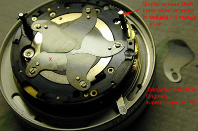
Opening up to check out the shutter blades and activator ring.
The iris comes off as a complete module. First unscrew the lens rear
element.
Then just remove two countersunk and one pillar screw.
You will need to remove the brass cotter from the shutter release shaft
but the cotter of the shutter-cocking shaft can remain. Do NOT - repeat
NOT remove either of the circlips on these shafts. In particular, removal
of the shutter release shaft circlip will make lots of extra work because
the shaft will then drop and the shutter release interface with the self-timer
beneath, will displace. You would then have to dismantle the lensblock
from the front to access the escapements,remove the timer escapement,
reposition the shutter release fork, fit the circlip - and reinstall the
self timer escapement. You have been warned ;-)
In my malfunctioning shutter, I was to find it jammed in the cocked position.
As soon as I attempted to lift the uppermost blade with tweezers the shutter
gave a sigh of relief and chucked the blades all over the room. So before
even touching the blades make a quick and dirty sketch of the overlap
direction as related to blade shape.
Upon gathering up the blades from the fish-tank, and various other landing
sites I began doubt my mathematics ability.
I had six blades - but there are only five fulcrums on the activator ring.
It was of course the uppermost blade which had cause the explosion when
I attempted to lift it off. It was therefore the sixth blade and it is
this which had caused the jam.
Note that the first blade to be installed has a turned-up tip which can
be seen through the front lens element. The sixth blade therefore shares
the same fulcrum -albeit with the other four blades sandwiched between
the two.
I quickly cleaned and polished the first five blades and installed them.
The sixth I decided to discard since I could see no logic in its presence.
The shutter then worked like a charm. I can only assume that Yashica adopted
this Citizen shutter configuration as an "off the shelf" component
which had been designed with six blades for some other camera application
(and reason).
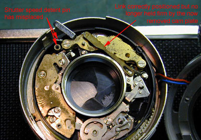
As to checking the shutter escapements from the camera front.
Remove the shutter cam-plate with gossamer touch.
See the pic here. The one inch brass link between the shutter release
mechanism and the self-timer is held flat in position only by the pressure
of the shutter cam plate sandwhich. It will surely displace slightly when
the cam plate is lifted.
You will also almost certainly find the spring-loaded shutter speed detent
pin displaced. Both are shown in my pic.
In summary .......... the Minister III is nicely engineered - particularly
its rangefinder. But it is not quite an intuitive stripdown job if the
shutter blades are your object of address. I hope these few notes and
pics will be helpful to Minister III adventurers.
|