| Author |
Message |
    
Rm6
Tinkerer
Username: Rm6
Post Number: 1
Registered: 11-2010
Rating: N/A
Votes: 0 (Vote!) | | Posted on Saturday, November 13, 2010 - 10:19 am: | 


|
Hi! I recently acquired a Vitomatic II (not IIa) and unfortunately discovered that the rangefinder wasn't aligned. Infinity was off and when checked with a tape measure 6' was off as well.
Through other posts on this site I've managed to get the top off and successfully adjusted the vertical via this square screw:
http://goo.gl/Ntp9s
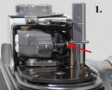
But nothing really happens when I try to adjust the horizontal using this screw with the spring around it:
http://goo.gl/Lw6pu
So is that the correct screw for horizontal adjustments? The rangefinder patch moves a little bit, but it never aligns at infinity or at 6' and the patch always hangs to the right of the real image.
According to this earlier post by Ethostech there's the possibility that the rangefinder objective has been flipped?
https://kyp.hauslendale.com/classics/forum/messages/15681/12884.html?1217997723
If that's the case...I don't know where to begin. I don't even know what that part is. :-)
Is this little piece of glass the rangefinder objective?
http://goo.gl/7JJ1e
If that is it...how do I go about getting to it? I can't figure out which screws to take out, or in which order. Also, is it possible to do without having to re-cement the viewfinder back together?
Any help is greatly appreciated. Thanks! |
Steve_s
Tinkerer
Username: Steve_s
Post Number: 173
Registered: 07-2006
Rating: N/A
Votes: 0 (Vote!) | | Posted on Saturday, November 13, 2010 - 01:16 pm: |
|
I'm pretty sure that is the correct screw for the horizontal adjustment, but I seem to remember from when I adjusted mine a couple of years ago that it doesn't behave in quite the linear way you might expect. I think it acts as a fine adjustment and only works over a limited range. Outside its range it may seem to have very little effect.
Try turning the screw anti-clockwise for a few turns, then turn clockwise half a turn at a time, checking to see what difference it has made, if any. |
Steve_s
Tinkerer
Username: Steve_s
Post Number: 191
Registered: 07-2006
Rating: N/A
Votes: 0 (Vote!) | | Posted on Saturday, December 03, 2011 - 12:17 pm: |
|
Since this thread seems to be the only one that turns up in searches for "vitomatic rangefinder adjust" I thought I should update it in the light of recent experience. Ignore what I said in my previous post! The rangefinder on my Vitomatic II has never been quite right, so I decided to have another go at it. I attempted to follow my own advice above, and found that like the OP I could never quite get the images to align at infinity using the screw shown in picture '1'. The images would get a little closer as I turned the screw clockwise, but they never coincided and as I continued to turn it they would start to get further apart again. This is NOT the infinity horizontal adjustment!
To start the job, take off the top cover. This is very easy on the Vitomatic; just 3 screws, one hidden behind the wind lever. You probably won't need to take off the meter, but if you do, remove the cover over the selenium cell (one screw), and then take out 2 screws, one down the gap between the cell and the meter body, and one long screw at the '5 o'clock' position. Remove the meter with aperture set to f22.
After examining the RF mechanism I found the infinity adjustment. It is not easy to adjust and impossible to photograph. There are 2 plates down inside the front of the RF mechanism. They are locked together by a screw where they pivot together, and another screw in an adjustment slot, and they each have a 'V' slot so that you can adjust their relationship by slackening the screws and levering with a screwdriver in the V slots.
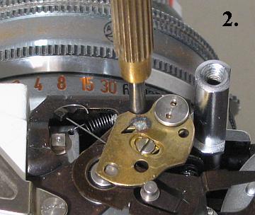
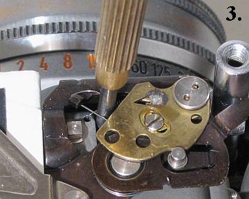
First slacken the pivot locking screw this is accessible through a hole which is where the screwdriver is placed in picture '2'. You can see this hole when you spring the brass plate of the metering mechanism back. Next, just partly re-tighten this screw so that the plates don't move when you slacken the screw at the adjusting slot end, which is below a couple of springs, where the screwdriver is placed in picture '3'. Next adjust the rangefinder infinity setting by levering in the V-slots. If the rangefinder image is not reaching coincidence at infinity, you need to move the upper plate clockwise relative to the lower. When you think it is right tighten both screws and check it again.
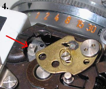
The vertical adjustment is the square adjuster shown in picture '4'. Turn it clockwise to raise the RF image. Fortunately, it seems to have little, if any, effect on the horizontal setting.
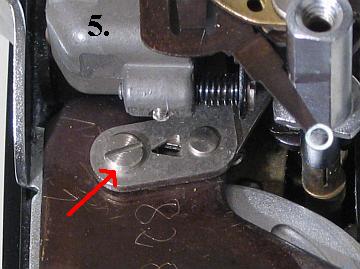
I think the adjustment arrowed in picture '5' is probably the close-up RF adjustment, though when I had the infinity correctly set, the close end was OK too, so I didn't try it. It works in the same way as the infinity setting, but without a lock-screw at the pivot. Undoubtedly it will interact with the infinity adjustment, but unless someone has been messing with it you will probably find, as I did, that it is OK when infinity is set.
So what is the adjustment shown in picture '1'? The adjustment alters the angle of a rectangular lens relative to the rangefinder optical block, and this lens turns with the block. My theory, for what it's worth, is this: If you look through the viewfinder at a vertical edge (I turned the camera 90° to 'portrait' position and looked at a horizontal telephone cable) and set the rangefinder so you can see 2 lines, you may find that if you move the camera slightly so you are not viewing the images directly on axis, the separation of the lines will change, meaning you could misalign the focus. It appeared to me that adjusting this screw seemed to minimise this effect. The optimum setting seemed to occur when the outer edge of the lens was about 1mm from the block. This does seem rather an over-engineered way of adjusting such a 'course' setting, so if anyone knows better, please post the information here! |
|