| Author |
Message |
    
Tylerwebb
Tinkerer
Username: Tylerwebb
Post Number: 6
Registered: 07-2010
Rating: N/A
Votes: 0 (Vote!) | | Posted on Saturday, August 07, 2010 - 03:15 pm: | 


|
I just got a great Canon AE-1 at the local thrift store. In really good shape, cleaning it up and trying to fix it just for fun, therefore not interested in Professional CLA.
The only problem so far is the meter. As soon as I depress the shutter button halfway, the meter drops to the bottom, underexposed. Even if I have it set to f:1.8 and 1 second shutter speed, pointed directly at a lamp it still says underexposed. I have taken the top off and everything seems to be working well, the tungsten cable is intact, as are all pulleys. The exposure wheel moves the cable easily, swinging the little arm under the rewind wheel.
Not sure how to proceed from here. I assume there is an electrical problem, a short or something, but can't see anything wrong. All the wires seem to be intact. I don't know much about the circuitry, but there are a few solders which do not have any wires connected to them, but there were no extras floating around in there either. Still waiting for my repair manual to arrive from ebay, but does anyone have any suggestions in the meantime?
I will post some photos in a bit if I can get anything applicable. |
Aphototaker
Tinkerer
Username: Aphototaker
Post Number: 218
Registered: 12-2009
Rating: N/A
Votes: 0 (Vote!) | | Posted on Sunday, August 08, 2010 - 10:52 am: |
|
Could you post the photos of the contacts with no wires? I can check with the camera I am refurbishing at present. Note that there are some contacts on the flex PCB meant as measurement points and may not have wires attached to them.
You can also download the AE1's service manual from the web. It describes the steps to go through in exposure measurement debugging. The manual should be available for free.
Just to be thorough, you did set a relatively high ASA speed, correct? |
Tylerwebb
Tinkerer
Username: Tylerwebb
Post Number: 7
Registered: 07-2010
Rating: N/A
Votes: 0 (Vote!) | | Posted on Sunday, August 08, 2010 - 03:38 pm: |
|
I will get a few photos right now. I don't really think the wireless contacts are broken, they look very clean and intact.
I googled every term I could think of for 20 minutes or more trying to get the AE-1 Service manual. I ordered a Canon Manual Collection from Ebay for $7 and it should be here in a few days. If you know somewhere that the manual would be available for free, please let me know. I think there should be a master index compiled of all manuals that anyone is aware of. Maybe a thread on here with links only.
I was using ISO 3200, f:1.8, Shutter speed 1 second and pointing it directly at a lamp, at a wall in direct sunlight, etc. Every other setting combo as well. |
Tylerwebb
Tinkerer
Username: Tylerwebb
Post Number: 8
Registered: 07-2010
Rating: N/A
Votes: 0 (Vote!) | | Posted on Sunday, August 08, 2010 - 04:16 pm: |
|
http://farm5.static.flickr.com/4073/4873540252_e8c10d4262_b.jpg
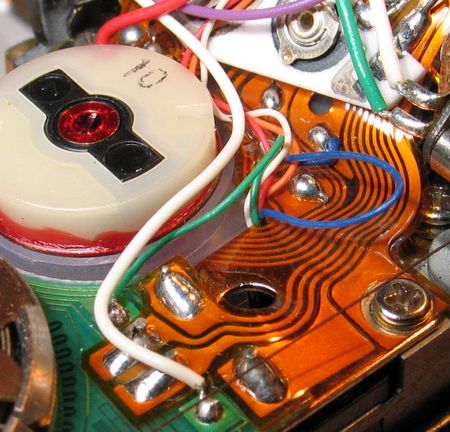
Red Dots indicate the leads/solders that do not have anything attached to them.
What are the Green Dots? I assume some type of calibration.
The blue dot is the coil which spins about 30 degrees clockwise when I depress the shutter button. This seems to signal the meter to drop to the bottom. |
Aphototaker
Tinkerer
Username: Aphototaker
Post Number: 220
Registered: 12-2009
Rating: N/A
Votes: 0 (Vote!) | | Posted on Sunday, August 08, 2010 - 05:30 pm: |
|
I will open up my AE-1 (it has a roll in it at present) in a day or two and confirm the red dots for you.
You are correct regarding the green dots.
The coil (blue dot) is the galvanometer and the aperture needle is attached to it.
I can send you the PDF file of the manual that I have if you wish (if yes, PM me your email address). The manual has some "rules of thumb" regarding the mechanics. e.g. the round thing under the rewind knob should have some particular angle in its markings for it to be set correctly. The quality of the manual is horrible though, the image are not very clear. It is quite readable, however. |
Aphototaker
Tinkerer
Username: Aphototaker
Post Number: 221
Registered: 12-2009
Rating: N/A
Votes: 0 (Vote!) | | Posted on Sunday, August 08, 2010 - 05:47 pm: |
|
I was searching for AE-1's photos with the top removed. Here is one:
http://cameracollector.proboards.com/index.cgi?board=auction&action=print&thread =1339
Looks like you are missing a cap or something from the galvanometer. |
Aphototaker
Tinkerer
Username: Aphototaker
Post Number: 222
Registered: 12-2009
Rating: N/A
Votes: 0 (Vote!) | | Posted on Sunday, August 08, 2010 - 06:17 pm: |
|
Meanwhile, here is another photo which shows that at least four of the contacts (lower right of your photo) with no wires are okay:
http://www.flickr.com/photos/cameraguy61/2449975770/
Note the while cover on the galvanometer though. Your doesn't have it in your photo.
They guy has written a nice article on how he refurbished his AE-1. The link is the following.
http://www.flickr.com/groups/canonae1/discuss/72157604783723877/ |
Tylerwebb
Tinkerer
Username: Tylerwebb
Post Number: 9
Registered: 07-2010
Rating: N/A
Votes: 0 (Vote!) | | Posted on Sunday, August 08, 2010 - 07:50 pm: |
|
Thank you very much! I removed the cover for the purpose of the photo, and to check the red wire connection etc. I have the cover intact, just not in photo. Check for PM... |
Aphototaker
Tinkerer
Username: Aphototaker
Post Number: 223
Registered: 12-2009
Rating: N/A
Votes: 0 (Vote!) | | Posted on Sunday, August 08, 2010 - 08:48 pm: |
|
Okay, that is comforting. So far, it looks as if all is well with the wires. But we can confirm this when I open mine's top after I finish the current roll.
You should have my email shortly. |
Aphototaker
Tinkerer
Username: Aphototaker
Post Number: 224
Registered: 12-2009
Rating: N/A
Votes: 0 (Vote!) | | Posted on Sunday, August 08, 2010 - 08:58 pm: |
|
You wrote:
"The only problem so far is the meter. As soon as I depress the shutter button halfway, the meter drops to the bottom, underexposed. Even if I have it set to f:1.8 and 1 second shutter speed, pointed directly at a lamp it still says underexposed."
NB: The camera's meter won't measure anything at shutter speed of 1s or longer! So you must experiment and test the meter at faster speeds (1/2s, 1/4s, ..., 1/1000).
If you find the same behavior at faster speeds as well, the scenario shows that the camera is seeing a pitch black image and wants you to open the aperture even further ... or, as you say, the camera is telling that the frame will be under exposed. Or, it is as if the SPC, the photo cell, is not detecting any illumination at all. So that is how I would go about checking for problems. |
Tylerwebb
Tinkerer
Username: Tylerwebb
Post Number: 11
Registered: 07-2010
Rating: N/A
Votes: 0 (Vote!) | | Posted on Sunday, August 08, 2010 - 09:52 pm: |
|
OK some great news, and some terrible news.
After reading Page 13 of the service thing you sent me, I reinstalled the Speed Knob as explained, slotting the coupler and then rotating counterclockwise until B gets to the index, then it dropped into place.
Re-Checking the meter with slow settings (1 second, and 1/2 etc) and ISO 3200, still same behavior. Then, I tried changing it to 1/1000 and iso 200 or something like that. Suddenly, the meter started working. It was in reverse however. I am in a relatively dark room with just a few lamps, and pointing it at the wall with no direct light yielded a meter reading of f:11 ISO 200 1/1000 which is definitely incorrect. So, it seems that something was, or is, backwards. Should be easy enough to figure out with a bit of logical thinking and trial and error.
However, when I was taking the speed-knob off, the force of the tension being released snapped my tungsten wire. It is broken off at the speed-wheel end and frayed for about 1/2 inch.
Like I said, I just barely did this maybe 5 minutes ago, haven't had a chance to research the fix yet.
Where do I get a replacement wire?
Edit: Service Manual explains replacement, sounds easy enough. But where to get the wire? It says "The tungsten wire can be ordered as a replacement part" but I don't find it anywhere. Can I just get the right length of generic tungsten wire and do it myself? |
Tylerwebb
Tinkerer
Username: Tylerwebb
Post Number: 12
Registered: 07-2010
Rating: N/A
Votes: 0 (Vote!) | | Posted on Sunday, August 08, 2010 - 10:09 pm: |
|
Also, I checked the calibration of the meter, the timing mark gives me a meter reading about in the middle, and is very responsive to adjustment. I am quite sure that it is electrically sound, was just a mechanical issue before, I assume a botched repair in the past that led to some weird misalignment of something, probably the wire itself. |
Aphototaker
Tinkerer
Username: Aphototaker
Post Number: 225
Registered: 12-2009
Rating: N/A
Votes: 0 (Vote!) | | Posted on Sunday, August 08, 2010 - 10:24 pm: |
|
Too bad the wire broke. I have never been in those waters myself so I can't advise where to go about obtaining one.
Searching the archives here or google is a very good start. I recall reading somewhere that a guitar wire of similar thickness could do the trick. Or you could try to get a dead AE-1 to cannibalize.
Some posters apparently have experienced this and know how best to proceed. Hope somebody responds here.
Here is a recent post on photo.net about the wire:
http://photo.net/canon-fd-camera-forum/00WnOk
Good luck! |
Tylerwebb
Tinkerer
Username: Tylerwebb
Post Number: 13
Registered: 07-2010
Rating: N/A
Votes: 0 (Vote!) | | Posted on Sunday, August 08, 2010 - 10:47 pm: |
|
There are places to buy tungsten wire for relatively cheaply online. It seems like it is also used for fly fishing lures, so maybe the fishing shop. I saw that post on photo.net, but thanks for putting it here. (Edit: Maybe its not so easy to get, lots of bulk suppliers, maybe i will check out guitar string)
Also, just calibrated the meter using my DSLR meter as a guide. Interesting adjustment. Twisting the Galvanometer (clockwise=+Exp) and (ccw=-exp) very very sensitive just a few degrees was all it needed. |
Aphototaker
Tinkerer
Username: Aphototaker
Post Number: 226
Registered: 12-2009
Rating: N/A
Votes: 0 (Vote!) | | Posted on Sunday, August 08, 2010 - 11:32 pm: |
|
I am not sure I understand what you mean by twisting the galvanometer. Could you explain in some more details how you did this? Also, how do you calibrate the meter with the wire broken (what is the ISO, what is shutter speed)?
Thanks. |
Tylerwebb
Tinkerer
Username: Tylerwebb
Post Number: 14
Registered: 07-2010
Rating: N/A
Votes: 0 (Vote!) | | Posted on Monday, August 09, 2010 - 01:11 pm: |
|
The whole Galvanometer housing rotates, and this is the meter calibration. The little white cover that is missing from my photos has little slots for spanner. I could just grab the little black part in between though, very very carefully being sure to avoid touching any connections, and twist it with my fingers.
The Functional Resistor has a calibration point, a little gold arrow which is aligned exactly opposite of the lens side of camera. Setting the little needle/arm of the Functional Resistor to this little gold arrow is equivalent to 1/60th Second ISO 100 setting. So, since the wire is broken, it just sits in that position very easily.
I set it to that position, and then using my DSLR with Shutter Speed 1/60th and ISO 100, I started taking photos using the AE-1 Meter suggested aperture. After about 10 minutes of fiddling with the Galvanometer, back and forth just a few degrees very carefully, it was giving acceptable results.
This is explained in detail (the technical aspects, not really the application, which I just had to figure out) on page 27 of the Service Manual. |
Aphototaker
Tinkerer
Username: Aphototaker
Post Number: 227
Registered: 12-2009
Rating: N/A
Votes: 0 (Vote!) | | Posted on Monday, August 09, 2010 - 02:46 pm: |
|
Wonderful explanation. Thanks for the feedback. I think I will use this method to fix mine's meter; it is off by 1 stop.
I gather there are pots (potentiometers, variable resistors) to calibrate the meter. I wonder which is a more advisable method to adjust the meter, using the pots or rotating the meter.
I am almost done with the roll. You may expect photos of the top of the camera either later tonight or by tomorrow night.
Regards. |
Aphototaker
Tinkerer
Username: Aphototaker
Post Number: 228
Registered: 12-2009
Rating: N/A
Votes: 0 (Vote!) | | Posted on Monday, August 09, 2010 - 10:16 pm: |
|
Here are the photos you had requested earlier. Let me know if you want more.
Macro shot of the circuit near the viewfinder. Shot is taken from behind the camera, from left of the viewfinder.
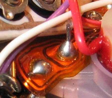
Macro shot of the circuit near the variable resistors (left of front of the prism). The red wire is going into the white galvanometer cover. The shot is taken from the front of the camera.
From the looks of it, your camera's circuit looks okay. |
Brcamera
Tinkerer
Username: Brcamera
Post Number: 1
Registered: 08-2010
Rating: N/A
Votes: 0 (Vote!) | | Posted on Tuesday, August 10, 2010 - 01:50 am: |
|
Moving the galvanometer housing does not actually calibrate the meter, just the meter readout. You could remove the galvanometer and the camera would work fine although you would not know what F stop the camera is using. Calibrating is done using the pots on the board. |
Aphototaker
Tinkerer
Username: Aphototaker
Post Number: 229
Registered: 12-2009
Rating: N/A
Votes: 0 (Vote!) | | Posted on Tuesday, August 10, 2010 - 08:26 am: |
|
Brcamera: I understand what you mean. In my case, the meter appears to be off by a constant stop throughout the EV range. So I was assuming that that the constant offset may just be fixed by rotating the galvanometer.
Meanwhile, found this post while searching for something related:
https://kyp.hauslendale.com/classics/forum/messages/6900/5028.html
"... If meter is working but just not accurate,ie error is relatively constant over many lighting conditions,then the adjustment is to rotate the whole galvanometer body until needle indicates correct aperture for test light source.The galvo body has spanner slots for this purpose. "
Regards. |
Brcamera
Tinkerer
Username: Brcamera
Post Number: 5
Registered: 08-2010
Rating: N/A
Votes: 0 (Vote!) | | Posted on Tuesday, August 10, 2010 - 10:29 am: |
|
Well, early SLR (Pre A series Canon) and rangefinder cameras used what was call a "trap needle" system for auto exposure where the galvanometer needle was actually locked down in its position at the moment of exposure and this determined the aperture that the camera would select. The genius of the Canon A series is that they converted inputs, including light, into a digital number so the "trap needle" system was no longer needed and in fact the galvanometer itself was no longer needed for camera operation other than to tell the human operator what was going on with the aperture. So in your case, you need to set up your tungsten wire and calibrate it using the index mark on the circuit board on the rewind side (the large screw on the rotating contact is an eccentric for adjusting) and see where that leads you. Make sure to properly thread the tungsten wire through the pulleys by the eyepiece. If after this the meter is still off, you will need to adjust via the pots, but quite frankly, I found it rare to have to adjust the meter on the AE-1 by any large amount and I have had hundreds of them on my repair bench. Correct routing of the tungsten wire often was all that was needed for repair. And after the meter is correct, you can then adjust the galvanometer if needed but this should be the last step..
Regards,
Bill |
Aphototaker
Tinkerer
Username: Aphototaker
Post Number: 230
Registered: 12-2009
Rating: N/A
Votes: 0 (Vote!) | | Posted on Tuesday, August 10, 2010 - 10:37 am: |
|
Brcamera: got it!
Meanwhile, I have noticed some crusty buildup on the SPC. I am making another post about it.
Thanks. |
Brcamera
Tinkerer
Username: Brcamera
Post Number: 7
Registered: 08-2010
Rating: N/A
Votes: 0 (Vote!) | | Posted on Tuesday, August 10, 2010 - 11:30 am: |
|
I'm new to this forum so I don't know if this has been posted before, but the Canon A series of cameras has a neat feature that lets you see what F stop the camera has used on the last exposure (since the meter needle is only an indicator and might not be calibrated properly). Here is the technique:
With the lens on "A", make your test exposure. Then, without cocking the shutter, take the diaphragm ring off "A" and put it on the largest aperture setting (wide open). Push in the depth of field lever until it locks. Looking at the lens from the front, slowly turn the diaphragm ring towards minimum aperture and you will see the diaphragm blades close down. When turning the diaphragm ring no longer makes any change on the diaphragm blades movement, this is the F stop that the camera used on the last exposure as it is "memorized" by the camera body!
Bill |
Aphototaker
Tinkerer
Username: Aphototaker
Post Number: 233
Registered: 12-2009
Rating: N/A
Votes: 0 (Vote!) | | Posted on Tuesday, August 10, 2010 - 12:58 pm: |
|
Yes, that is a great little trick indeed. I don't recall having read this as a debugging step, but I do recall reading in the manual that to view DOF, one has to charge the camera first otherwise the previous shots f stop will be used ... or something to that effect.
Neat!
Thanks. |
Tylerwebb
Tinkerer
Username: Tylerwebb
Post Number: 15
Registered: 07-2010
Rating: N/A
Votes: 0 (Vote!) | | Posted on Tuesday, August 10, 2010 - 01:20 pm: |
|
Thanks for the info, that is very interesting! I just got cd with manuals on it, so I've got some heavy reading to do.
Where do you get new tungsten wires Brcamera? That is my most pressing concern right now. I will probably be ordering a 10m spool if there are no other suggestions. |
Aphototaker
Tinkerer
Username: Aphototaker
Post Number: 234
Registered: 12-2009
Rating: N/A
Votes: 0 (Vote!) | | Posted on Tuesday, August 10, 2010 - 01:26 pm: |
|
Another choice is a kevlar fishing line. See this post for more info and ideas:
https://kyp.hauslendale.com/classics/forum/messages/6900/5605.html?1133455907 |
Aphototaker
Tinkerer
Username: Aphototaker
Post Number: 235
Registered: 12-2009
Rating: N/A
Votes: 0 (Vote!) | | Posted on Tuesday, August 10, 2010 - 01:42 pm: |
|
Tyler, I went over the document again (the one I sent your earlier). After you explained the procedure regarding the position of the functional resistor, I read it again and now I understand it better.
I confirmed the various position of the mechanism on my camera and they all agree with what you describe. So that rules this out as the reason for the difference of 1 stop my camera's measurement.
Read the procedure how to go about replacing the wire as well. Seems straightforward. I was able to remove the ASA dial and the white disc with the wire, let the functional resistor unwind and then reinstall the wire. Thanks to your explanations and the manual, it was quite easy.
BTW, as you have found out ,the manual I sent you is not searchable. I uploaded it to my Google docs (it can convert scanned PDFs to readable text PDFs!), but the Google's conversion tool failed to create a searchable PDF  I guess the document's quality is just too bad. I guess the document's quality is just too bad. |
Tylerwebb
Tinkerer
Username: Tylerwebb
Post Number: 16
Registered: 07-2010
Rating: N/A
Votes: 0 (Vote!) | | Posted on Tuesday, August 10, 2010 - 09:56 pm: |
|
I went to the local fishing shop and asked about Kevlar Line, at which they looked rather confused. I explained to them what it was for and showed them the old tungsten wire, and explained I needed something with a small diameter and maximum tensile strength. They brought me some line made of Dyneema which seems great. I use Dyneema on a regular basis for rock climbing protection, and it is one of the strongest and lightest materials for climbing strength materials. Anyway, I trust my life on it all the time, might as well trust my camera's metering system.
Impressions: Seems very strong, easy enough to work with, handles much like the tungsten wire actually. Similar size and is a Matte grey color which looks nice against the yellow pulleys.
I am having a minor struggle with getting all the tensions correct for the functional resistor spring barrel and correct alignment with settings on speed knob.
I have found the reason why it was initially metering backwards (and it is still doing it, trying to figure out a solution right now, but at least I understand the problem...)
The line is wound around the speed selector knob, feeding out line as it is unwound which is then taken up by the spring barrel on the other side, as tension is relieved. Currently, between B-3200ISO and 1/60-100ISO everything is fine and it unwinds the right way. However, at this point all of the slack from the speed knob side is fed out and already taken up by the hungry spring. So, if I go any faster than this, to 1/500-100ISO for instance, then the line begins winding in the opposite direction, increasing tension on the line and therefore being equivalent to 1/4-100ISO.
I think the solution is to wind the speed knob once clockwise prior to connecting to the spring barrel. This is not mentioned in the repair manual however. Any thoughts? I am going to try it and report back. |
Aphototaker
Tinkerer
Username: Aphototaker
Post Number: 237
Registered: 12-2009
Rating: N/A
Votes: 0 (Vote!) | | Posted on Tuesday, August 10, 2010 - 10:07 pm: |
|
Here is how I understand this and how I did this on my camera (did not replace the wire, but took out and repositioned the white disk below the shutter speed dial):
1. You might need to try different lengths (use the broken tungsten as the first estimate).
2. Make a tiny knot on one end of the wire and use it to secure the wire on the white disc (do not insert the disk on the shutter speed rod yet).
3. Take the other end of the wire, make it go around the groove in the outer side of the functional resistor disk, through the slot near the accentric post, around the post and then on to the tab where you need to secure it with a few turns.
4. Now do the winding and the positioning:
a) The functional resistor would need a winding of around 1 and a quarter turns clockwise (with the wire in its outer groove. Hold the resistor there.
b) Thread the wire through the five pulleys and insert the white disc onto the shutter speed rod (its slot will point forwards between 10'o clock and 11'o clock position wrt to the front of the camera).
c) Gradually release the functional resistor. Reseat shutter speed/ASA dial the usual way and check for the functional resistor's alignment with the little golden arrow index mark on the PCB at 1/60s and ASA 100. If it doesn't line up, you may need to either turn the eccentric post to correct it or repeat the procedure with a different wire length.
I will post a photo shortly with a legend. |
Aphototaker
Tinkerer
Username: Aphototaker
Post Number: 238
Registered: 12-2009
Rating: N/A
Votes: 0 (Vote!) | | Posted on Tuesday, August 10, 2010 - 10:30 pm: |
|
CORRECTION in my last post, step 4-a: to install the wire, the functional resistor dial would need to be wound by turning it in counter-clockwise direction for a turn and a quarter.
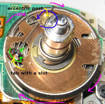
Here is a photo of the functional resistor (it is in the position where the shutter speed dial is removed).
1 (Magenta): The wire goes around the outer edge of the dial and goes in through the slot in the edge of the dial.
2 (Blue): Coming through the slot of the dial edge, it goes around the eccentric post and continues on ...
3 (Green) .. toward the tab with a slot. It goes through the slot and is wound (as far as I can see) around the tab. The black stuff is probably glue to hold the wire there.
NB: The position shows (photo taken from front of the camera) the dial when the shutter speed dial is removed. The eccentric post is pointing toward the back of the camera, or at 6'o clock position if seen from behind the camera. With wire broken or uninstalled, it would be unwound and there will be no spring tension, the dial would have turned clockwise for around 1 and a quarter turn, i.e. the post would be then at around 9'o clock position and without any spring tension.
 |
Tylerwebb
Tinkerer
Username: Tylerwebb
Post Number: 17
Registered: 07-2010
Rating: N/A
Votes: 0 (Vote!) | | Posted on Wednesday, August 11, 2010 - 01:03 am: |
|
Got it finished! Very happy, everything seems functional, only problem is I need to calibrate the meter readout vs the actual meter.
http://farm5.static.flickr.com/4080/4881083697_921934f41c_b.jpg
This is what I ended up doing and it worked quite well and pretty easily:
1. I used the entire piece of line, maybe 3-4 feet worth (it will be cut to size as the final step), which was wrapped tightly around the stick from a Q-Tip . I tied a large knot, made up of several simple overhands tied in the same place to make a larger knot ball. I inserted this into the small slot on the black disk beneath the speed wheel. There is a tiny piece of brass, like a shim, which helps to hold the knot in place. I added a drop of super glue to this shim. Let it dry for a bit.
2. I put the disk in place, making certain that the line ran to the outside edge at a 45 degree angle, this will allow the line to be wrapped counter clockwise, remaining on the outside edge of the disk instead of flipping to the inside at certain settings.
3. Set the Speed Wheel to B-3200ISO. This is the setting which should ALWAYS ALWAYS ALWAYS be used when installing or taking off the speed wheel. If I had used this setting a few days ago when disassembling the speed ring, my tungsten wire would not have snapped in the first place. Using any other setting, especially the fast settings like 1/1000-25 would make the disk as tightly wound as possible, just waiting to violently un-spin.
4. Be sure the shutter speed setting (The inside wheel beneath the speed disk with 2 slots) is set to B as well, just so it will match the setting on the speed wheel. To do this, put tweezers or pliers into the holes on either side of the shutter speed control and twist it clockwise until it stops. The final click will be longer than the rest.
5. To install the speed wheel, put the outside-edge tab into the notch, this will cause the speed wheel to be off-kilter, since the 2 shutter speed control tabs at the center of the speed wheel will not sit in place yet. Twist the speed wheel slowly counter-clockwise, pressing down gently until the inner tabs fall into the shutter speed control holes. The line or wire should now be in a position similar to as shown in the photo above.
6. Run the line behind the first pulley, under the second, over the third and fourth, then under the fifth.
7. Twist the functional resistor counter clockwise at least 1 full turn. This will engage the spring and it will resist. When the small arm golden colored arm with the little pin (which is connected to the bottom of the functional resistor) becomes aligned 45 degrees clockwise from the small gold alignment mark (directly behind the functional resistor center post) then it is time to attach the wire. Pull the wire around clockwise until it lines up with the little notch and tab. If you put the wire under the tab and immediately switch directions, the frictional bend of the wire will hold the functional resistor in place and keep it from un-spinning. Chances are, alignment is incorrect. To get correct alignment, change the speed-dial setting to 1/60-100ISO. This will cause the functional resistor to rotate a bit counter-clockwise (while the disk beneath the speed wheel is also rotating counter clockwise. This is important to understand that a faster speed causes counter-clockwise rotation, and a slower speed causes clockwise rotation)
8. Carefully, slowly, release some tension on the wire where it attaches to the functional resistor. I had to twist my functional resistor another 1/2 rotation counter-clockwise to get the little needle arm to align with the index mark. It seems like a bad idea to rotate it clockwise, since this could cause potential loss of tension later on. I actually aligned the needle a few degrees to the counter-clockwise side of the index mark, because everytime I attempted to connect it to the eccentric post, I would invariably lose a few degrees. By over-compensating I ended up with perfect alignment.
9. Quick checklist before proceeding:
The Shutter Speed is set to 1/60-100ISO
The functional resistor needle part is aligned with the index marker (which indicates 1/60-100ISO BTW)
The wire wraps around the outside edge of both the speed wheel disk, and the functional resistor.
The functional resistor has plenty of tension in case of a slow setting. If there is a setting without adequate tension, the wire will fall off of the pulleys and cause lots of trouble later.
Check all settings between B-3200ISO ~ 1/1000-25ISO. Double check. Watch the wire on the pulleys.
10. Wrap the Eccentric Post, then over to the tabs. Go through the slot between the tabs. Wrap several times. Cut with scissors, leaving 3-4 inches of slack to work with. Now is the time to check everything again. Tie 3-4 overhand knots which are touching one another, this will create a large knot. Continue wrapping until the knot sits beneath the tab. Apply a tiny drop of super-glue. When I say tiny drop, I mean it. Stray super-glue is the worst thing in the world besides Zombie Invasions. Bend the tabs down. Apply another tiny drop of super glue, just to the line/wire. You aren't trying to glue the wire to the tab, but rather to itself, reinforcing the wraps. Wait a bit for the glue to dry. Check everything again.
11. Re-assemble. Check everything again, then give yourself a high-five.
Thanks for the help everyone, especially aphototaker.
A few words about the exposure: I got a grey-shirt and put it under a lamp. I pretended to take several photos of the shirt, checking the meter readout versus the actual aperture used. (Thanks alot for that tip BTW Brcamera!)
I then used my DSLR with the same ACTUAL settings as the AE-1 and the exposure looks perfect. The readout underexposes a bit. I will have to get in there and twist the galvanometer back a bit I guess until the readout matches. |
Tylerwebb
Tinkerer
Username: Tylerwebb
Post Number: 18
Registered: 07-2010
Rating: N/A
Votes: 0 (Vote!) | | Posted on Wednesday, August 11, 2010 - 01:08 am: |
|
Feels great to turn a thrift-store paper-weight into such a cool camera.
http://farm5.static.flickr.com/4096/4881765466_911289940f_b.jpg
If an admin reads this, can you please change the title of this thread to something appropriate for posterity, since I exclusively said "Not Tungsten Cable" when that ended up being the biggest problem after all? Thanks |
Aphototaker
Tinkerer
Username: Aphototaker
Post Number: 240
Registered: 12-2009
Rating: N/A
Votes: 0 (Vote!) | | Posted on Wednesday, August 11, 2010 - 07:25 am: |
|
Congratulations! Excellent job!
BTW, were the manuals on the CD any help?
Regards. |
Tylerwebb
Tinkerer
Username: Tylerwebb
Post Number: 19
Registered: 07-2010
Rating: N/A
Votes: 0 (Vote!) | | Posted on Wednesday, August 11, 2010 - 09:24 am: |
|
The one you sent was the best of the bunch, which was actually on the cd as well. I will have to browse through them all some more. I am sure that some of the others will eventually be useful, there are like a hundred or so. The Service Manual that you sent me was missing a page, however, and the one on the CD is intact. Did i get corrupt download or are you missing a page too? |
Aphototaker
Tinkerer
Username: Aphototaker
Post Number: 241
Registered: 12-2009
Rating: N/A
Votes: 0 (Vote!) | | Posted on Wednesday, August 11, 2010 - 10:10 am: |
|
No, it is corrupted on my copy as well. Could you send me the good one?
Thanks. |
Tylerwebb
Tinkerer
Username: Tylerwebb
Post Number: 20
Registered: 07-2010
Rating: N/A
Votes: 0 (Vote!) | | Posted on Wednesday, August 11, 2010 - 01:01 pm: |
|
http://docs.google.com/leaf?id=0B2PcbyTsa5QSZDQwZTdkMDEtMWY5NS00ZGM1LTg1MDEtZjAw NTAyNGZmNTcx&sort=name&layout=list&num=50 |
Aphototaker
Tinkerer
Username: Aphototaker
Post Number: 243
Registered: 12-2009
Rating: N/A
Votes: 0 (Vote!) | | Posted on Wednesday, August 11, 2010 - 06:04 pm: |
|
Thanks for the document, much appreciated. If I can find a good OCR application (perhaps Adobe can do it?), I will try to convert it to a searchable text PDF file. |
Tylerwebb
Tinkerer
Username: Tylerwebb
Post Number: 26
Registered: 07-2010
Rating: N/A
Votes: 0 (Vote!) | | Posted on Sunday, August 15, 2010 - 06:27 pm: |
|
I've been reading the repair manual as much as possible trying to figure out how to truly recalibrate the meter.
Brcamera, what do you mean by adjusting the pots?
I have adjusted the 4 little knobs on the left side of pentaprism, and have attained acceptable exposures by trial and error, will this potentially cause any unseen effects? |
Teraforce88
Tinkerer
Username: Teraforce88
Post Number: 21
Registered: 08-2009
Rating: N/A
Votes: 0 (Vote!) | | Posted on Sunday, August 15, 2010 - 08:12 pm: |
|
Those 4 little knobs you're talking about are the potentiometers, or "pots" for short.
On a side note, the way you calibrated your AE-1 was basically how I calibrated my Minolta XE-7, although I had a "good" camera meter as a reference. When you don't have all that fancy calibration equipment, trial-and-error against a known good camera is the best you can do. (A service manual and knowing which pot does what certainly helps, too) |
Aphototaker
Tinkerer
Username: Aphototaker
Post Number: 249
Registered: 12-2009
Rating: N/A
Votes: 0 (Vote!) | | Posted on Sunday, August 15, 2010 - 08:36 pm: |
|
IIRC, Canon cameras (others too I suppose) are adjust with potentiometers (pots or variable resistors, named as VRn in the documentation) in different lighting conditions.
I am not familiar with AE-1, but the A-1 documentation shows that the meter is adjust by changing two resistors. One changes the slope of the response of the meter wrt illumination (EV) and the other changes the offset of the response (high or low).
The other method used by cameras is to adjust the meter reading under varying illumination. One VR changes the output for high illumination, 15 EV, another VR changes it for medium illumination, 9 EV(?), and a third for dim illuminaiton, 5 EV (?).
Both method basically adjust the response of the meter so that it fits different levels of illumination (i.e. the metering error is smallest at different levels).
I took a look at AE-1's documentation (the one you sent me) but for now am not able to find if there is a method given there.
Sorry, can't help more at this time. I actually never did these adjustments on an AE-1. |
Camerawiz
Tinkerer
Username: Camerawiz
Post Number: 1
Registered: 08-2010
Rating: N/A
Votes: 0 (Vote!) | | Posted on Monday, August 16, 2010 - 07:34 pm: |
|
I wasn't going to write anything since I so much enjoyed reading the rabbit trails you all were running around. But I finally had to help you out.
The tungston wire is calibrated asa 100 1/60th and align the mark on the back of the functional resistor.
Next, place a 47 0hm resistor across the dedicated flash terminal and ground, close the meter switch and adjust the meter until it reads f4.
next, using a known light source with at least 3 levels, EV9, EV12, EV15 with a normal lens on the camera set the camera to 15th and asa 100 and read the f-stop at lv 9. Next go to 1000th and lv 15 and read the f-stop. The difference is adjusted using the pot closest to the rear of the camera, vr1. go between these 2 levels until the reading is the same. (should be near 5.6 +- 1 stop. When this is equal use lv12 and 125th and using the middle pot, vr2, adjust the meter to 5.6. The front pot is used to adjust the under exposure light.
I have found many of these cameras have a white coating on the Sbc cover which gives low meter readings. scrape it off and it should work well. |
Aphototaker
Tinkerer
Username: Aphototaker
Post Number: 250
Registered: 12-2009
Rating: N/A
Votes: 0 (Vote!) | | Posted on Monday, August 16, 2010 - 10:56 pm: |
|
Most of what Camerawiz wrote appears to agree with the basic method as I understand it. In his description of the method, VR1 changes the slope of the meter's response line and VR2 changes its vertical offset.
However, I don't think the following is correct.
"place a 47 0hm resistor across the dedicated flash terminal and ground, close the meter switch and adjust the meter until it reads f4."
The correct value of the resistance to get f/4 reading is 4.7 KOhms. This the equivalent resistance of a Canon dedicated Speedlite when set at f/4 aperture. When this resistance is applied between the hot shoe contact and ground of the camera and the shutter is released, the lens should close down to f/4. |
Inwo
Tinkerer
Username: Inwo
Post Number: 3
Registered: 01-2011
Rating: N/A
Votes: 0 (Vote!) | | Posted on Monday, February 14, 2011 - 05:42 pm: |
|
Here are the cheapest digital camera batteries, quality assurance, fair trade,
such as samsung battery charger
nikon battery charger
canon battery charger and so on
If you can not find the battery type you want to buy,
you can use the search function top right corner if you want to buy can go to .good luck |
Teraforce88
Tinkerer
Username: Teraforce88
Post Number: 31
Registered: 08-2009
Rating: N/A
Votes: 0 (Vote!) | | Posted on Thursday, February 17, 2011 - 02:01 pm: |
|
^^WTF?? |
Br1078lum
Tinkerer
Username: Br1078lum
Post Number: 61
Registered: 11-2010
Rating: N/A
Votes: 0 (Vote!) | | Posted on Thursday, February 17, 2011 - 05:27 pm: |
|
Terraforce, it's better to contact Margaret about the spammers (as I've already done) than adding to their post. Sometimes it takes a while before they are removed.
PF |
Ren
Tinkerer
Username: Ren
Post Number: 1
Registered: 07-2010
Rating: N/A
Votes: 0 (Vote!) | | Posted on Saturday, February 11, 2012 - 08:45 pm: |
|
Hi! I don't know if this discussion is still alive, but above Tylerwebb wrote 'Be sure the shutter speed setting (The inside wheel beneath the speed disk with 2 slots) is set to B as well, just so it will match the setting on the speed wheel. To do this, put tweezers or pliers into the holes on either side of the shutter speed control and twist it clockwise until it stops. The final click will be longer than the rest."
Can someone explain with a photo the "inside wheel" & the two slots ? |